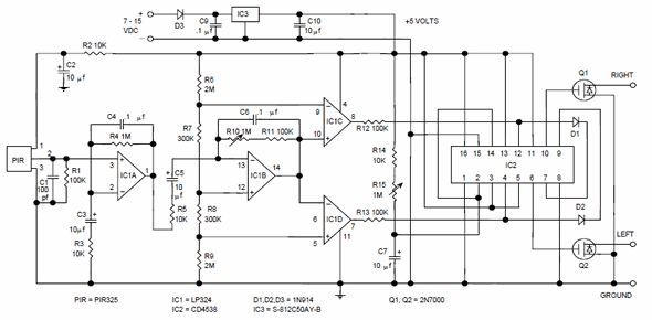
Light sensor circuit working operation. Along with the pir sensors a simple circuit is used with it.
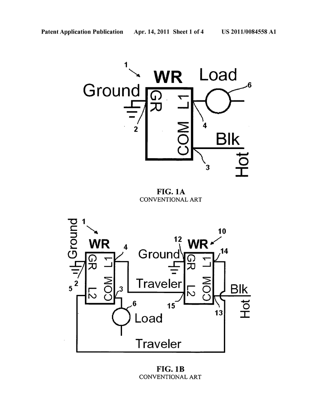
Motion Sensor Switch For 3 Way Light Circuit And Method Of
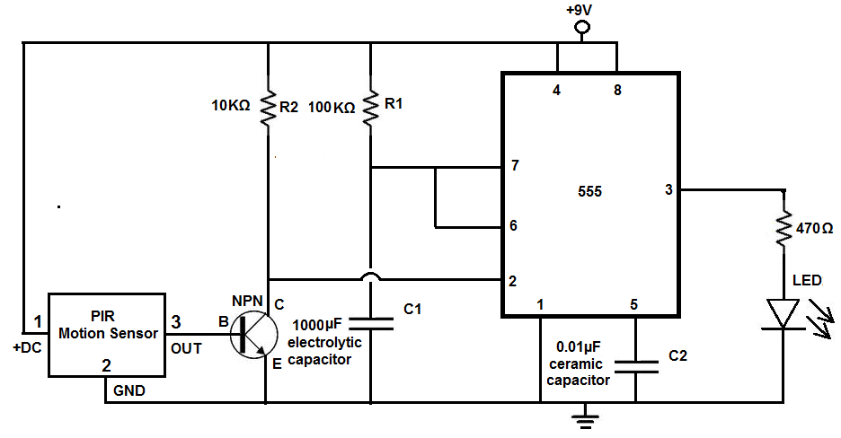
Motion sensor light control circuit diagram. In this article we will be discussing a very useful and reliable security device called infrared motion detector circuitthe circuit can be used for detection of moving object or body with the use of infrared sensors like ir pir etc. Working of the circuit is simple and straight forward. This automatic staircase light circuit switch on the staircase lights automatically when someone enters on the stairs and gets off after some time. The 12v dc supply required for the whole circuit can be fed from any standard 12v ac mains adaptorbattery. There are two important components in this circuit first is pir sensor passive infrared sensor and second is relay. A 230v ac supply is provided to the load in this case the load is represented with a lamp.
Motion detector circuit diagram. It reveals the elements of the circuit as streamlined shapes and also the power and also signal connections between the tools. Motion detector circuit explanation. Share on tumblr staircase lights are needed only when we walk through it other wise we dont need it traditional way is using two way switch to control the staircase light. The pir passive infrared sensor detects the motion of person and gives short duration pulse output with the help of this sensor. So we manually turn onoff the light here is a simple and best solution to go automatic.
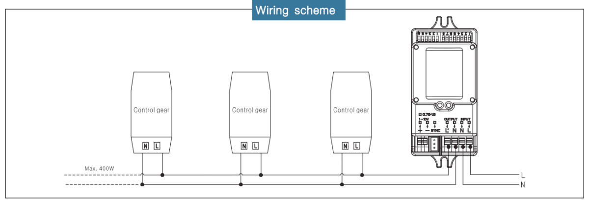
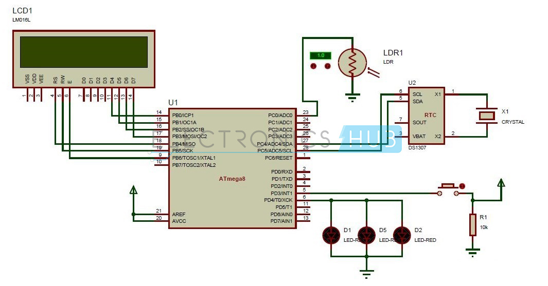
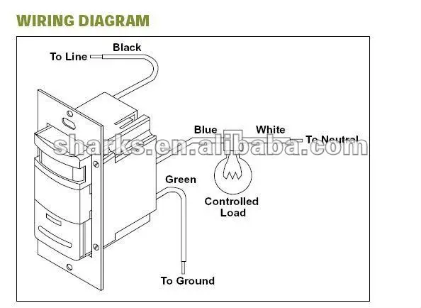
Nowadays security is the first and foremost requirement of everyones life. The light sensor circuit is an electronic circuit designed using light sensor ldr darlington pair relay diode and resistors which are connected as shown in the light sensor circuit diagram. The ir sensor will make the high frequency beam of 5 khz with the help of 555timer which is set to astable multivibrator mode at the transmitter section. The ir sensor will produce the high frequency beam which is received by the photo resistor at the receiver section. Variety of motion sensor light wiring diagram. A wiring diagram is a simplified conventional pictorial depiction of an electrical circuit.
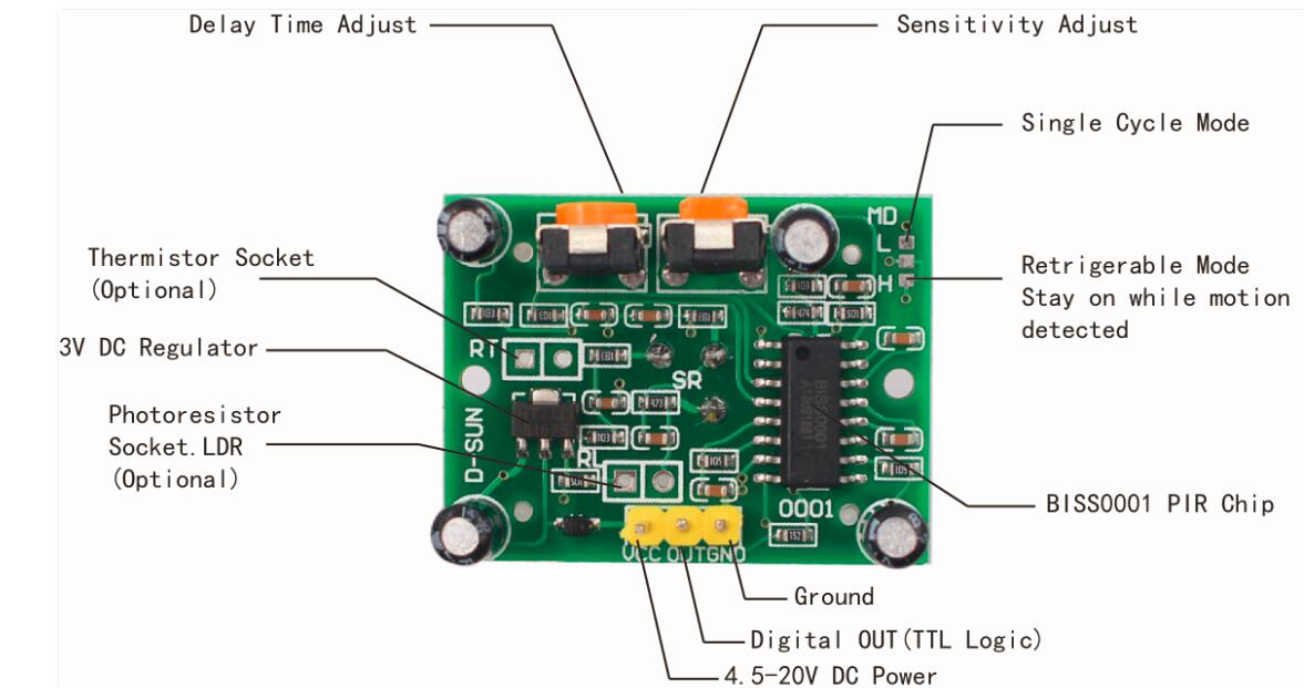
The sensor when purchased it comes with the default mode h which means that the circuit switches on the light when somebody moves within the zone and it remains on for preset time and after the preset time lapses if the sensor could still detect motion it does not switch the light off in the absence of a moving target it switches off. Circuit diagram of the pir motion sensor light and switch based on sb0061 shown here can be used for security or corridor lighting in power saving mode.

