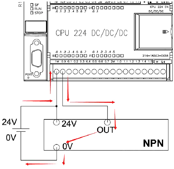
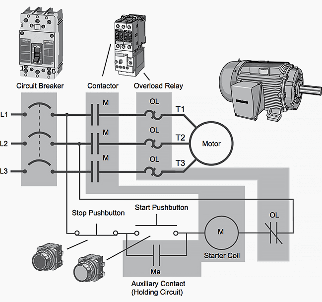
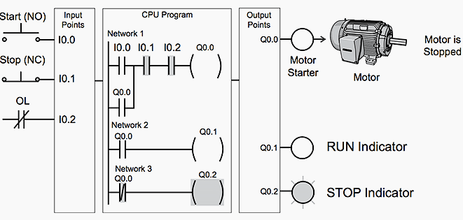
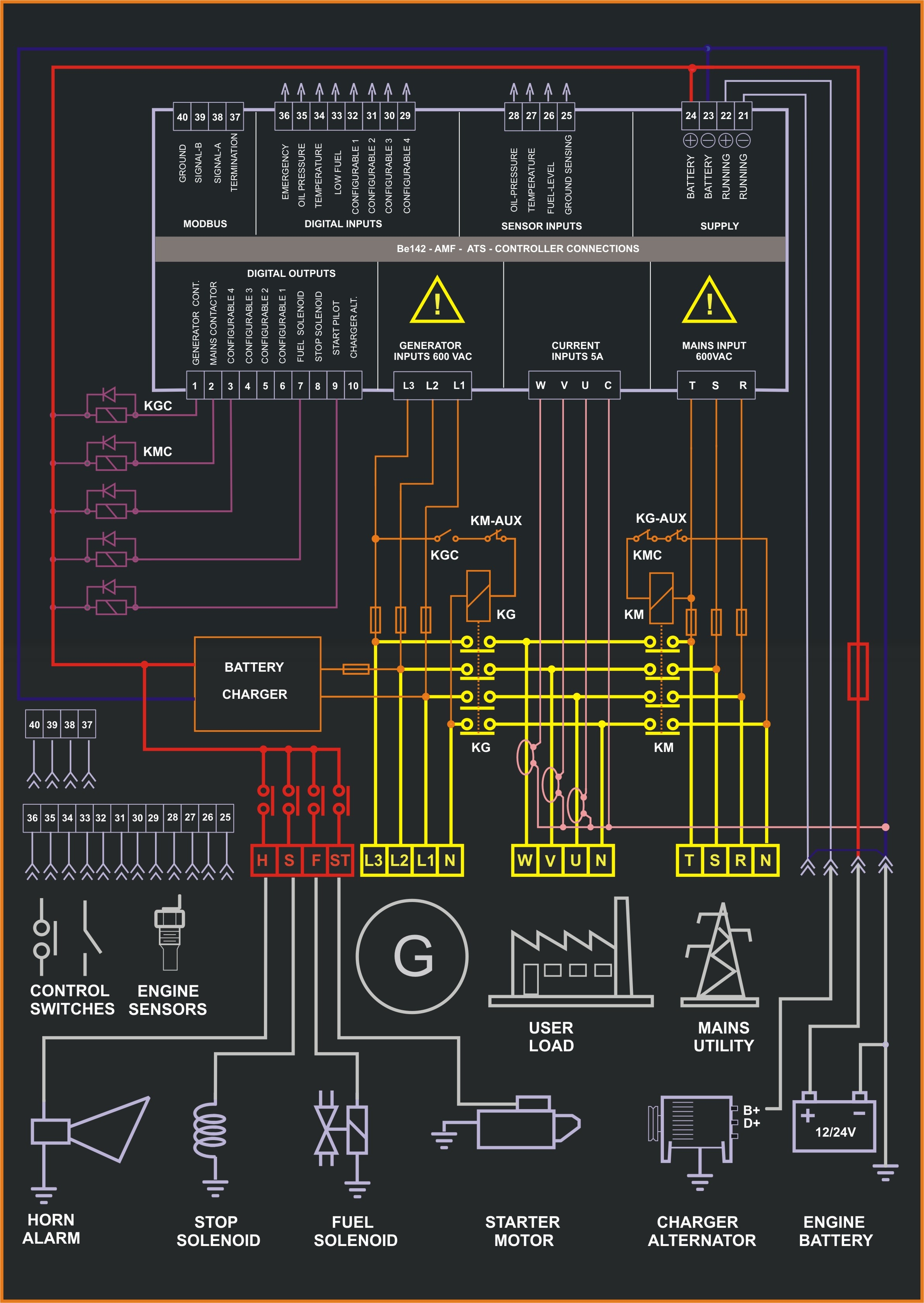
Figure 5 below shows a schematic diagram for a plc based motor control system similar to the previous motor control example. Connect the main power supply to the power supply module in the control panel through a relay terminal block.

Gm 8370 Wiring Diagram Home Work Wiring Diagram Micrologix
Mitsubishi plc wiring diagram pdf. A plc progr am created by the format of circuit diagram ladder diagram is also stored in the program memory of the plc with the format of instruction list program list. Wiring precautions warning after wiring attach the included terminal cover to the module before turning it on for operation. Mitsubishi electric programmable controllers must be installed in control panels. Do not remove the film during wiring. A wiring diagram is a simplified conventional photographic representation of an electric circuit. The conversion between instruction list program list and circuit diagram ladder diagram can be done by using the programming software on a personal computer.
When drilling screw holes or wiring make sure that cutting and wiring debris do not enter the ventilation slits. 166388 15082013 version e mitsubishi electric industrial automation. But it does tend to become more complex. Melsec fx family programmable logic controllers beginners manual fx1sfx1n fx2nfx2nc fx3gfx3gcfx3ge fx3s fx3ufx3uc mitsubishi electric art. This figure shows the e stop wired to cutoff power to all of the devices in the circuit including the plc. The operation of pressing a pushbutton corresponds.
111 ladder diagrams as an introduction to ladder diagrams consider the simple wiring diagram for an electrical circuit in figure 111a. Caution individually ground the fg terminal of the progr ammable controller with a ground resistance of 100 or less. Remove it for heat dissipation before system operation. Be sure to remove the dust proof sheet from the plcs ventilation port when installation work is completed. From entering the module during wiring. Assortment of plc panel wiring diagram pdf.
When including a plc in the ladder diagram still remains. Mitsubishi plc wiring diagram pdfview and download mitsubishi fx3g 14mres installation manual online. It shows the elements of the circuit as streamlined shapes as well as the power as well as signal connections in between the tools. Wiring fixed contact wiring wiring circuit closed circuit open wiring contact wiring spring spring spring before button is pressed in return position after button is pressed in operating position spring circuit open note 1 actuate here means to force operation from normal state of rest. Failure to do so may cause fire equipment failures or malfunctions. A programmable logic controller is a specialized computer used to control machines and processes.
The ladder diagram graphical programming language is standardized by the plcopen organization and thereby the symbols used in ladder diagramssince ladder logic is a graphical programming language the plc programs written in ladder logic are a combination of ladder logic symbols. Failure to do so may result in electric shock.


