Working of electrical interlocking. Many large pieces of equipment are powered directly from high voltage lines.

Wiring Diagram Contactor H1 Wiring Diagram
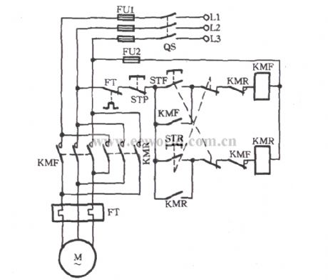
Magnetic contactor interlocking diagram. 11 bg06 10 a460 60 for mini contactor bg06 with one no contact and 460vac 60hz coil. This is an electromagnetic type contactor and it can operate automatically. 240 volts ac and 480 volts ac are commonly used for these large pieces of. Contactor wiring and i hope after this post you will be able to wire a 3 phase motor i also published a post about 3 phase motor wiring with magnetic contactor and thermal overload relay but today post and contactor wiring diagram is too simple and easy to learn. We will use a contactor an auxiliary contact block an overload relay a normally open start pushbutton a normally closed stop pushbutton and a power supply with a fuse. The coil of the contactor can be powered indifferently in ac or dc.
Magnetic contactor httpsbitly3eucp11 bisitahin ang ating fb page httpsgoogly8ys68 kung may mga katanungan kayo ay comment lang kayo sa baba at sasagutin ko hangat kaya ng aking nalalaman. A detailed look at the design and application of reversing contactors. Therefore the operation of this contactor is safe compared to manual contactor. 2 days ago i wired 380 to 440 volts contactor for a 3 phase motor and save these images of contactor in pc. The following diagram depicts 3 phase non reversing motor control with 24 vdc control voltage and manual operation. The design of this type of contactor is most advanced among all other types of contactors.
It requires a small amount of control circuit to turn on and off the load. How to wire a contactor. Magnetic reversing starters generally change t leads and to reverse the motor. And motor m1 starts to run. 11 bg06 10 a230 for mini contactor bg06 three poles with one no contact and 230vac 5060hz coil. Complete the order code only with the.
The direction of rotation of any three phase motor can be reversed by changing any two motor t leads l1 figure 291since the motor is connected to the power line regardless of which direction it operates a separate contactor is needed for each directionif the l3 reversing starters adhere to nema standards t leads 1 and 3 will be changed figure 292. When we push the on 1 button to energies the m1 contactor or starts m1 motor then circuit complete through fuse overload relays trip link off push 1 and on push 1. These lines far exceed the 120 volts ac standard in most homes. This is some of my best work yet. Its is important to. Auxiliary electrical interlocking can be accomplished by connecting the normally closed contacts on one contactor in series with the coil of the other contactor.


