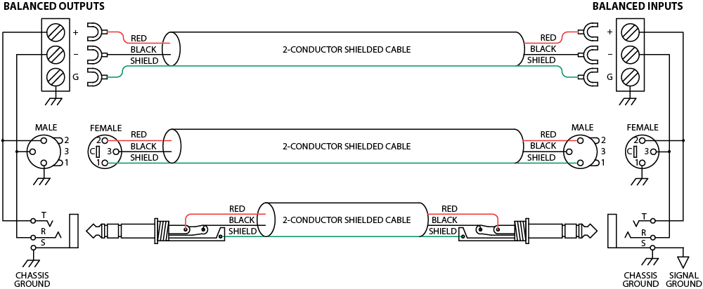
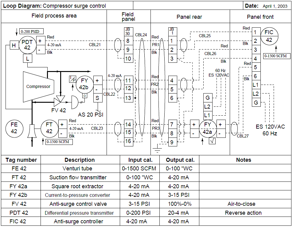
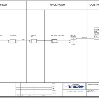
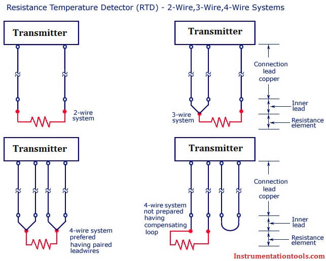
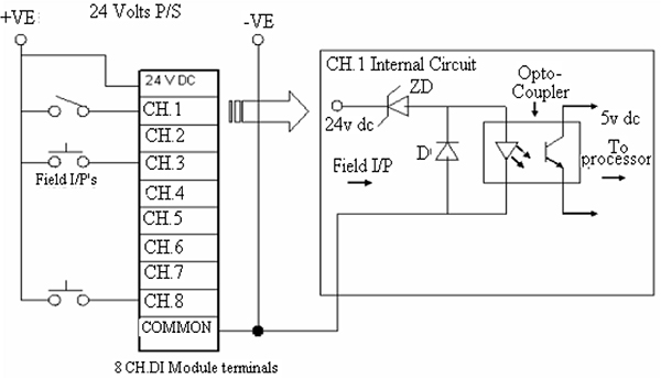
Wiring charm io in spi introduction the user experience on a project with over 50000 io while several wiring methods were used on the project this presentation will focus on the use of electronic marshalling reasons for using electronic marshalling on the project. When a loop diagram shows you exactly what wire color to expect at exactly what point in an instrumentation system and exactly what terminal that wire should connect to it becomes much easier to proceed with any troubleshooting calibration or upgrade task.

Plc Timer Instructions Ladder Logic Plc Programming Timer
Loop wiring diagram instrumentation pdf. Emerson was the mic and the mac on the project. Loop diagrams are fairly constrained in their layout as per the isa 51 standard. 1 identification of the loop and loop components shown on the pids. The process is illustrated in sections. Loop drawing and wiring diagram conversion involves a semi automatic process. Loop diagram helps us to read the wiring connections from field instruments to system cabinet.
Find the top 15 loop diagram questions here. Although wiring data can be imported the intricate nature of instrumentation usually prevents a fully automated approach and so wiring is still performed manually to make sure it matches the intended design. Loop wiring diagram instrumentation pdf wiring diagram is a simplified tolerable pictorial representation of an electrical circuitit shows the components of the circuit as simplified shapes and the facility and signal links amongst the devices. These set of drawings are more detailed than process and instrument diagrams pids. Instrumentation diagrams are used for understanding the process system. 2 word description of loop functions within the title.
Loop diagrams are fairly constrained in their layout as per the isa 51 standard. When a loop diagram shows you exactly what wire color to expect at exactly what point in an instrumentation system and exactly what terminal that wire should connect to it becomes much easier to proceed with any troubleshooting calibration or upgrade task. Loop diagram symbols and pids pids and loop diagrams pids and loop diagrams are construction and documentation drawings that depict the flow of the process and illustrate the instrumentation control and measurement interactions wiring and connections to the process. Instrument loop diagrams are also called instrument loop drawings or loop sheets. A pid gives you an overall picture of how the process functions but sometimes you need more specific information about how instruments and. Loop diagrams are the most detailed form of diagrams for a control system and thus it must contain all details omitted by pfds and pids alike.
Other principal components of the loop to be shown and identified under isa 51 instrumentation symbols and identification. As a minimum an instrument loop diagram shall contain the information covered below. What are loop diagrams. Examine this loop diagram and answer the following questions. Pid that is piping and instrument diagrams or process instrumentation diagrams show you each loop in the system the instruments that comprise loop and identify all process variables.
