They exist remotely and control circuits with higher voltages which can be dangerous to the operator if controlled directly. Clap switch circuit using ic 555 timer without timer.

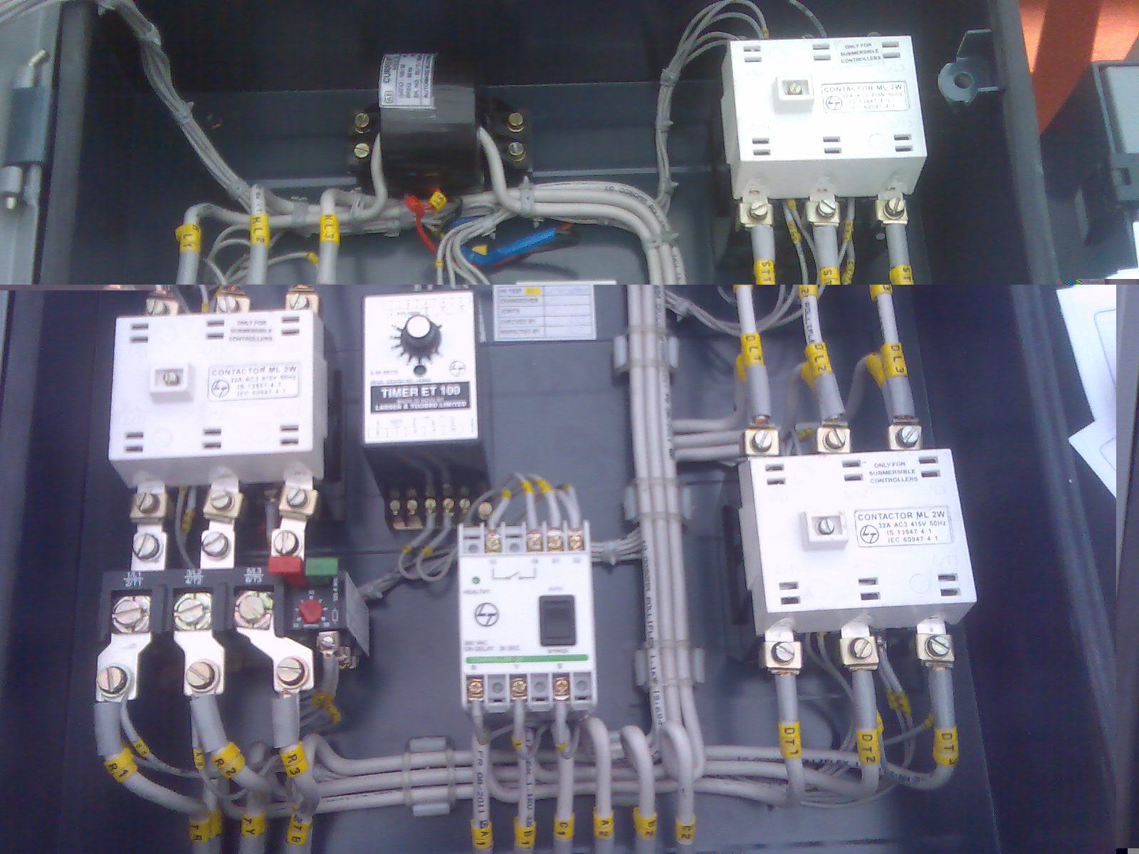
Wiring Up A Contactor Contactor Wiring Diagram With Timer
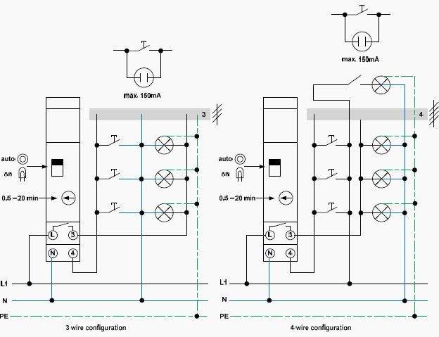
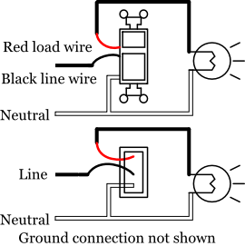
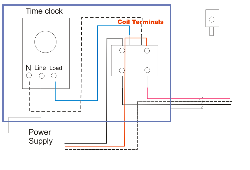
Lighting timer and contactor wiring diagram. On delay timer circuit diagram wiring diagram contactor with push button circuit diagram of delay timer on off power off delay timer circuit diagram 2 way lighting circuit triggering transformer push button fan switch light activated switch circuit diagram wd081 text. Collection of eaton lighting contactor wiring diagram. Each component should be placed and linked to other parts in particular manner. The lights connect to the output ports on the contactor. A wiring diagram is a simplified conventional photographic representation of an electrical circuit. The contactor will have space for the red power wires coming in from the photocell circuit breaker and lights.
Wiring diagram lighting contactor with photocell wiring diagram contactor wiring diagram. How do i do a wiring to a single phase contactor via photocell to the outside lights. With all the assist of this e book you can easily do your own personal wiring tasks. Lighting contactors are relay switches that control the flow of electricity through a circuit powering the lighting in a given area. One line diagram of simple contactor circuit control onoff circuit diagram of typical electrically held lightingheating contactor a contactor is an electr. It shows the components of the circuit as simplified forms and also the power and also signal connections in between the tools.
Youll be able to often rely on wiring diagram as an crucial reference that may assist you to save money and time. A lighting contactor switch operates at a lower but safer. Electrical earthing methods and types of earthing grounding. The black power wires will need to be tied together.


