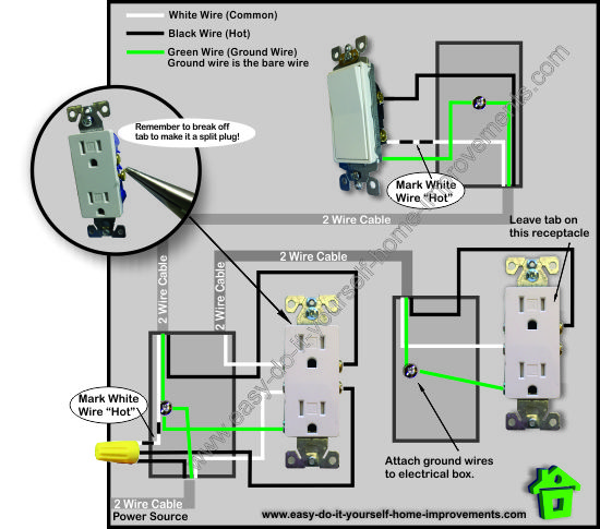
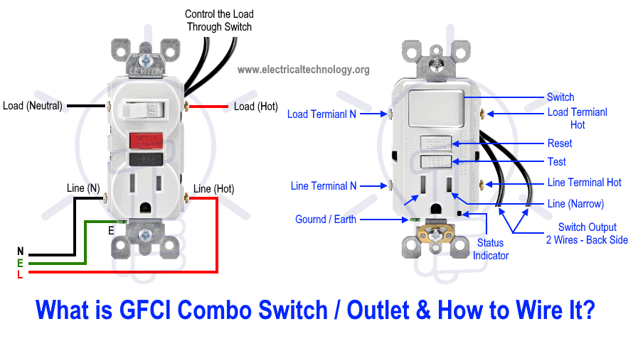
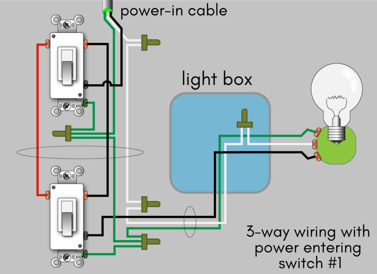
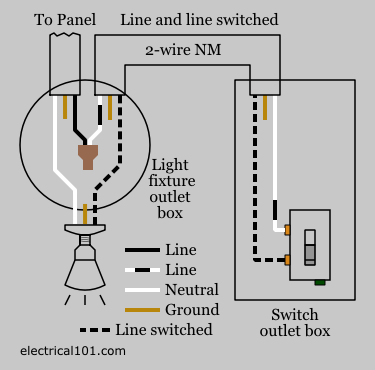
It reveals the parts of the circuit as streamlined forms and also the power as well as signal connections between the tools. Also shown is the half of the receptacle that is live at all times and the tab that must be cut in order to split the receptacles.
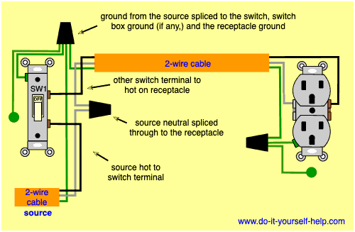
Wiring Diagrams For Switched Wall Outlets Do It Yourself
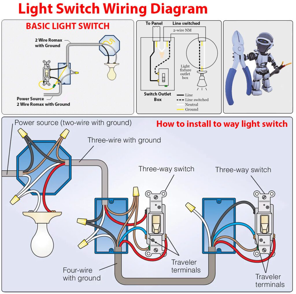
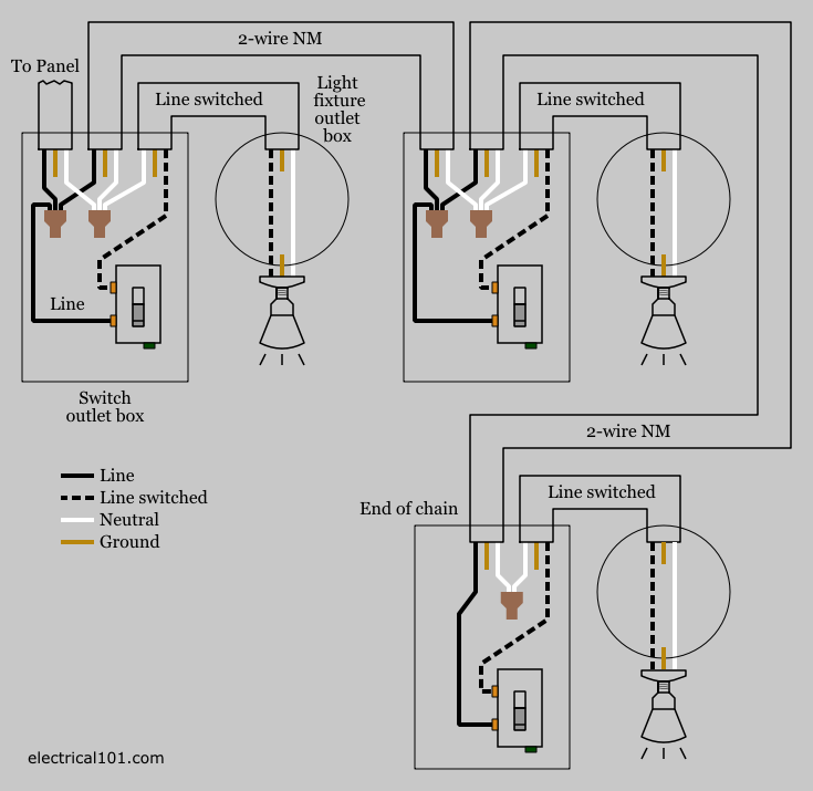
Light switch to outlet diagram. The incoming power from the outlet is attached to one of the light switch screw terminals and the black wire of the cable leading to the light fixture is attached to the other light switch screw terminal. A switch loop single pole switches light dimmer and a few choices for wiring a outlet switch combo device. One cant be too careful. My light switch wiring diagrams may be helpful to you. Also included are wiring arrangements for multiple light fixtures controlled by one switch two switches on one box and a split receptacle controlled by two. Each part should be set and linked to other parts in particular way.
The switch takes the hot from the middle receptacle here and 3 wire cable runs from there to the new switch location. Run the cable from the circuit breaker to the location of the electrical outlet. The toggle switch in the combo switch outlet controls the first light bulb while the single way switch controls the second bulb. How to wire an electrical outlet. Here a switch has been added to control an existing receptacle. Switch off the mains.
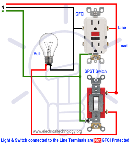
Components and devices are connected to the line terminals of gfci ie. Assortment of leviton switch outlet combination wiring diagram. Buy a single pole switch if one switch controls the lights or a three way if you have two switches controlling the same lights. A wiring diagram is a simplified traditional photographic representation of an electric circuit. Light switch to outlet wiring diagram light switch outlet combo wiring diagram light switch to outlet wiring diagram every electric arrangement is composed of various unique parts. You should switch off electrical power from the mains to avoid electrocution.
This page contains wiring diagrams for household light switches and includes. Switched split outlet wiring diagram for controlling the half of two duplex electrical receptacles by a wall switch without a neutral conductor. The diagram below shows the power entering the circuit at the grounded outlet box location then sending power up to the switch and a switched leg back down to the outlet. In the following diagram the above load mentioned before ie. Wiring for additional light. Notice that these outlets have the tab removed from the hot side or brass side of the outlet which allows the top half of the plug to be controlled only from the switch.
Otherwise the structure will not function as it should be. Add up the wattage of the bulbs in all the fixtures the switch controls to make sure it falls within the switch rating listed on the package or instructions. Your cable should be long enough to reach each socket. In short all the loads is gfci protected. They are connected to the direct main. Wall outlet switch wiring diagram.
Connections to the outlet are basically color to color for the blacks whites and green or bare ground wires. The hot source at the outlet is spliced to the black wire running to the switch and the hot wires running to the other outlets in.
