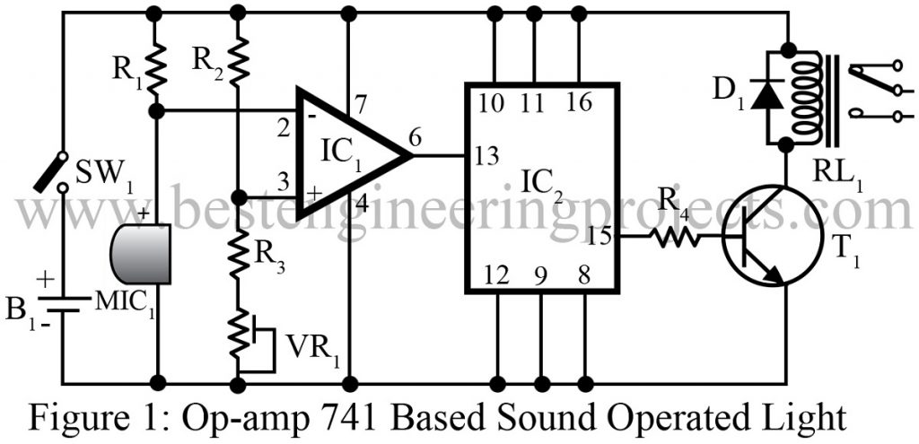
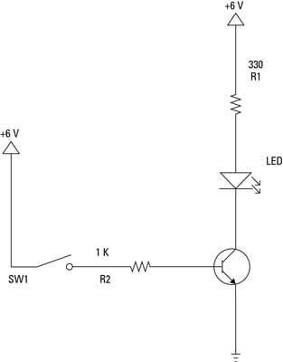
The circuit is based on a voltage comparator circuit wired around ic 1the non inverting in put of ic1 is given with a reference voltage of 6v using resistors r3 and r4. Multiple light wiring diagram.
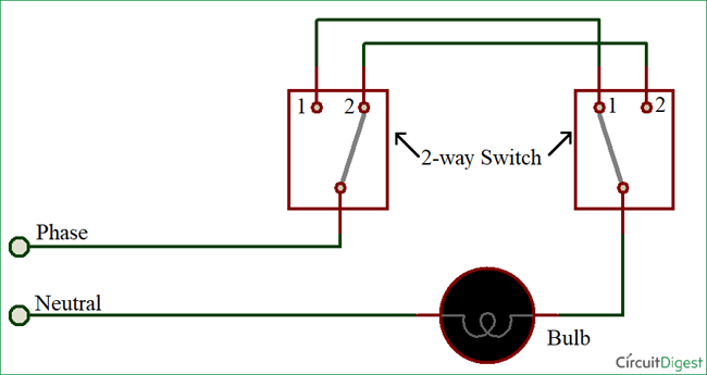
How To Connect A 2 Way Switch With Circuit Diagram
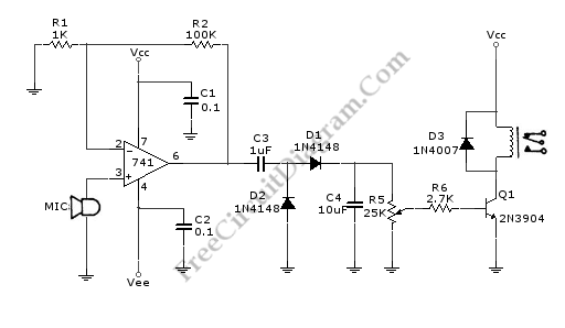
Light operated switch circuit diagram. Bridge rectifier resistors leds and capacitor. You can use this for automatic light switch for street light. A simple light activated switch description. The light activated switch circuit mainly consists of two components. The source is at sw1 and 2 wire cable runs from there to the fixtures. This circuit is a voice operated switch vox and designed for audio frequencies within a commercial telephone bandwidth of 100hz to 3000hz.
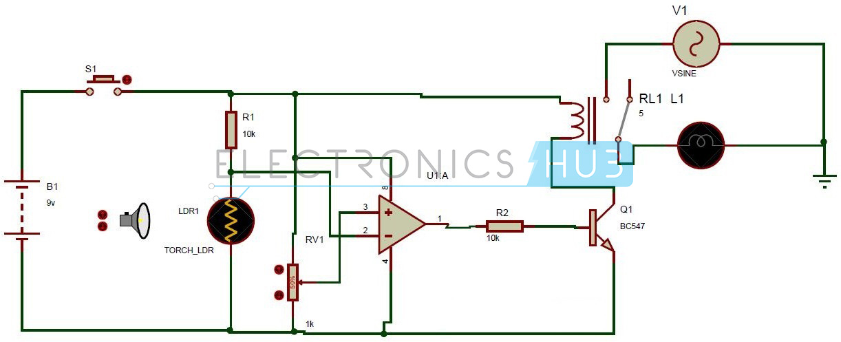
By this light activated switch in day light will automatically switched off and at night switch on light. Automatic on off light switch circuit this is a light operated relay circuit. All the components used in this circuit are easily available in market. It has two internally frequency compensated operational amplifiers. Light activated switch circuit design. Input amplitude is sensitive down to 10mv and the output comparator can drive a relay or interface to micro.
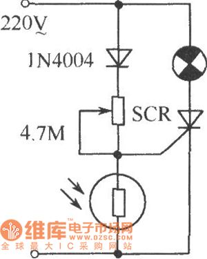
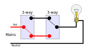
This simple circuit is based on simple components. Mains operated led circuit explanation. The comparator ic lm358 and the ldr. Light dependent resistorldr is used to operate the switching function of this circuit. This circuit is used to switched on light at night automatic and switch off in day light sunlight automatic. There are two methods of making 2 way switching connection one is 2 wire control and another is 3 wire control.
This diagram illustrates wiring for one switch to control 2 or more lights. So you can make this circuit and install in your homes and offices. There is no need to switch on or off manually. These kind of sensor circuits are widely employed in many applications and may come in handy when you intend to build a simple light sensing circuit. This is the circuit diagram of a light activated switch based on national semiconductors comparator ic lm 311 and a ldr. Usually the third wire passes the middle intermediate switch but is joined in a separate terminal block.
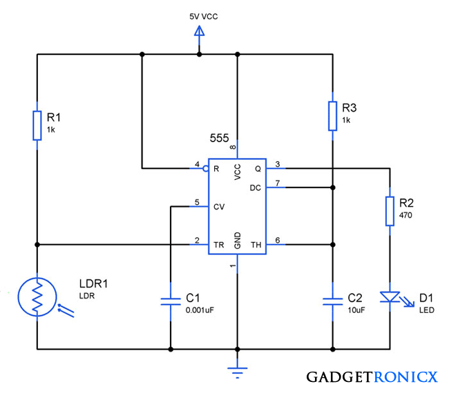
The lm358 ic has 8 pins and can have supply voltages ranging from 3 32 volts. Automatic light operated controlled switch circuit using ldr is very interesting circuit idea. Three way switching 3 wires. Light activated switch circuit light activating and deactivating switches are simple to build when you are provided with a ldr sensing element and 555 switch activator. This is also known as the conversion method since it is the easiest way to add a second light switch to an existing circuit. Three wires between the two end switches probably using 3 core and earth cable.
Two way switch can be operated from any of the switch independently means whatever be the position of other switchonoff you can control the light with other switch. The hot and neutral terminals on each fixture are spliced with a pigtail to the circuit wires which then continue on to the next light.

