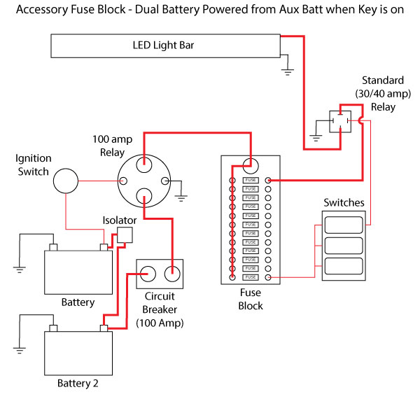
You must then switch to both in order to charge both batteries or have a separate diode type battery isolator. Dual battery isolator wiring diagram dual battery isolator circuit diagram dual battery isolator switch wiring diagram dual battery isolator wiring diagram every electric structure is made up of various unique pieces.

Boat Battery Isolator Switch Wiring Diagram H1 Wiring Diagram
Isolator switch wiring diagram. It shows the elements of the circuit as simplified forms and the power as well as signal connections between the devices. It shows the components of the circuit as simplified shapes as well as the power as well as signal connections between the devices. The switch lets you drain one battery then switch to another to start the engine. Each component should be placed and linked to other parts in particular way. With this sort of an illustrative guide youll be capable of troubleshoot prevent and complete your tasks with ease. A wiring diagram is a streamlined conventional pictorial representation of an electric circuit.
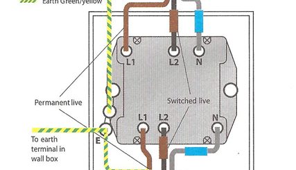
It is absolutely vital that the terminal screws do not clamp on the insulation of the cables. Assortment of battery isolator wiring schematic. Requires user to manually switch between batteries. No need to separate starterignition wiring from accessory wiring. Connect the new socket or switch as shown in the appropriate wiring diagram in these fitting instructions taking care that only the copper conductors enter the terminals. Dual battery isolator wiring diagram you will need a comprehensive expert and easy to comprehend wiring diagram.
Otherwise the arrangement will not work as it should be. A wiring diagram is a simplified conventional photographic representation of an electrical circuit. Assortment of multi battery isolator wiring diagram.


