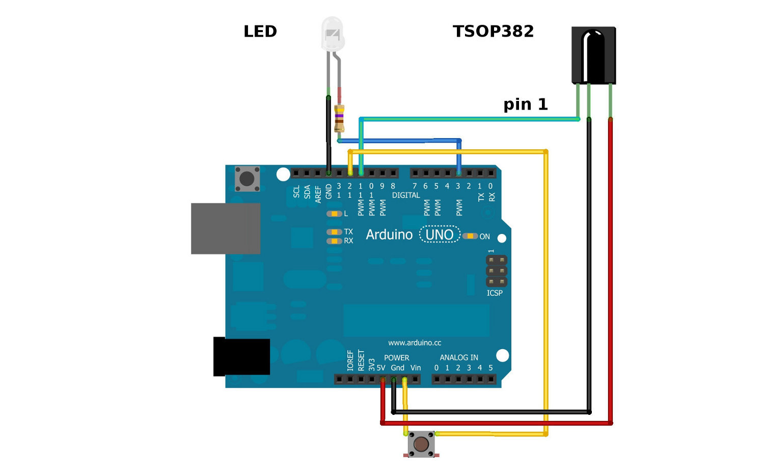
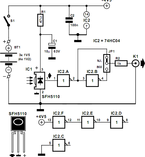
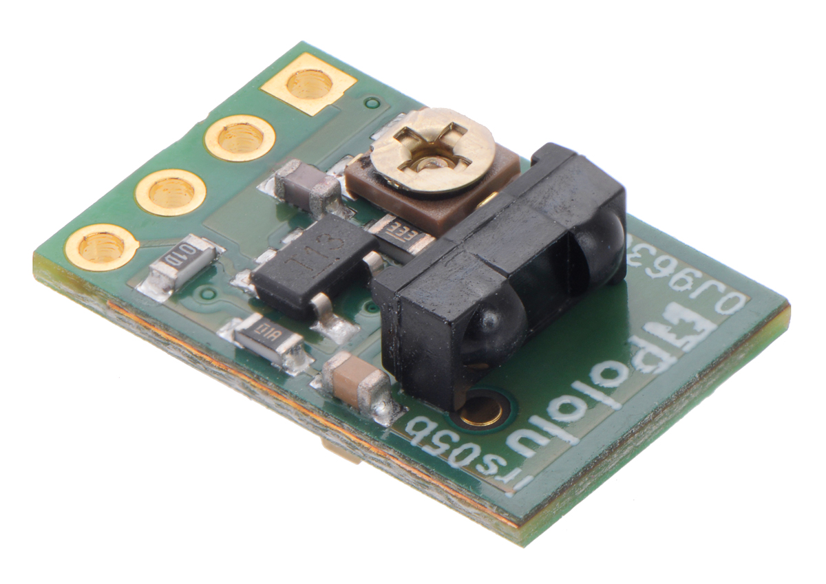
Tsop 1738 ir detector is used to receive the ir signals transmitted from remote. The sensor when purchased it comes with the default mode h which means that the circuit switches on the light when somebody moves within the zone and it remains on for preset time and after the preset time lapses if the sensor could still detect motion it does not switch the light off in the absence of a moving target it switches off.
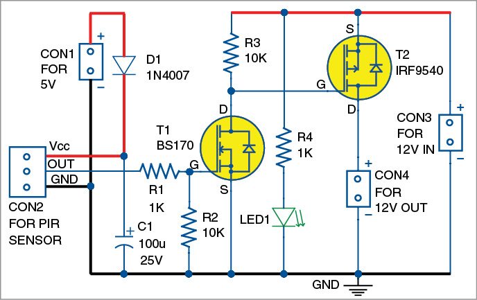
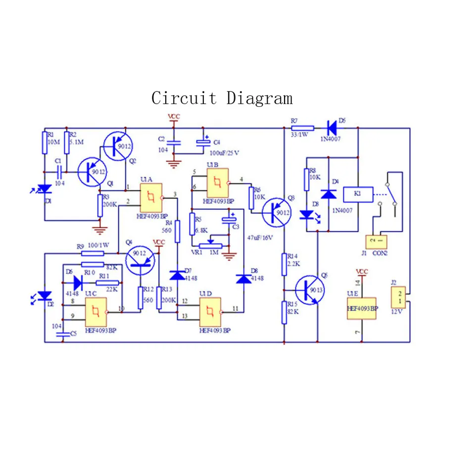
Ir Motion Sensor Relay Switch Detailed Project Available
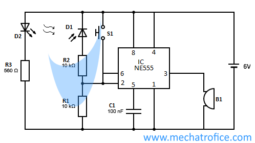
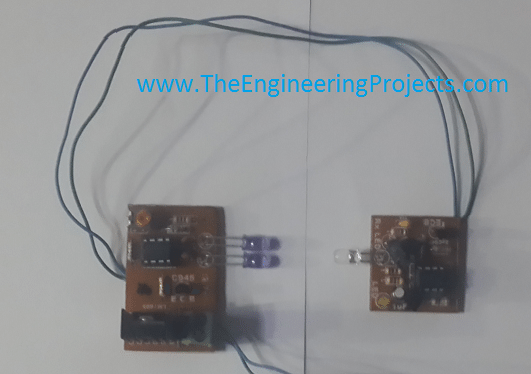
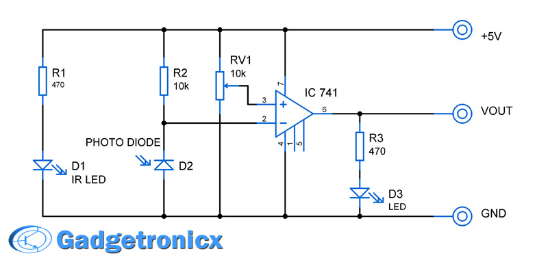
Ir sensor switch circuit diagram. Ir sensor ir sensor circuit diagram and working principle. This circuit can be used to switch on or off any 12 13 ac appliance using remote with 8 10 meter distance. Ir sensor basically consist an ir led and a photodiode this pair is generally called ir pair or photo couplerir sensor work on the principal in which ir led emits ir radiation and photodiode sense. An above image is an infrared proximity sensor circuit diagram. Ir led emits infrared light. An infrared sensor circuit is one of the basic and popular sensor module in an electronic devicethis sensor is analogous to humans visionary senses which can be used to detect obstacles and it is one of the common applications in real time.
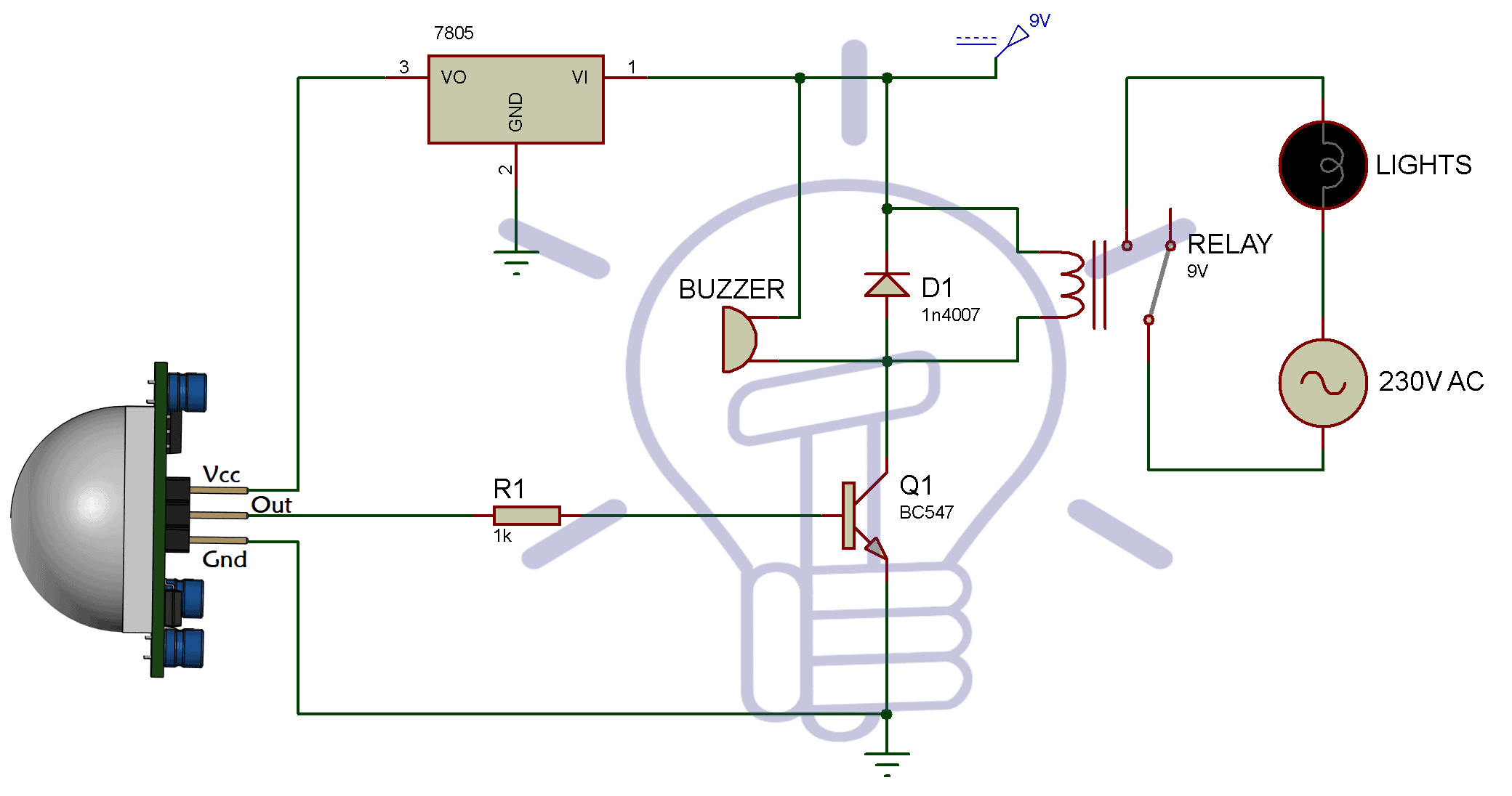
Circuit diagram of the pir motion sensor light and switch based on sb0061 shown here can be used for security or corridor lighting in power saving mode. Here i use only 5 bulb as load with circuit but 12 13 load can be connected. The circuit is simple and easy to make it has 2 transistors 4 resistors an ir led an ir phototransistor and a purple or white or green led use as an indicator so you can remove it if you want. Pinout of pir sensor. Ir sensor is very popular sensor which is used in many applications in electronics like it is used in remote control system motion detector product counter line follower robots alarms etc. Go through the given diagram of the pir sensor to understand its pin outs and arrangement in the circuit.
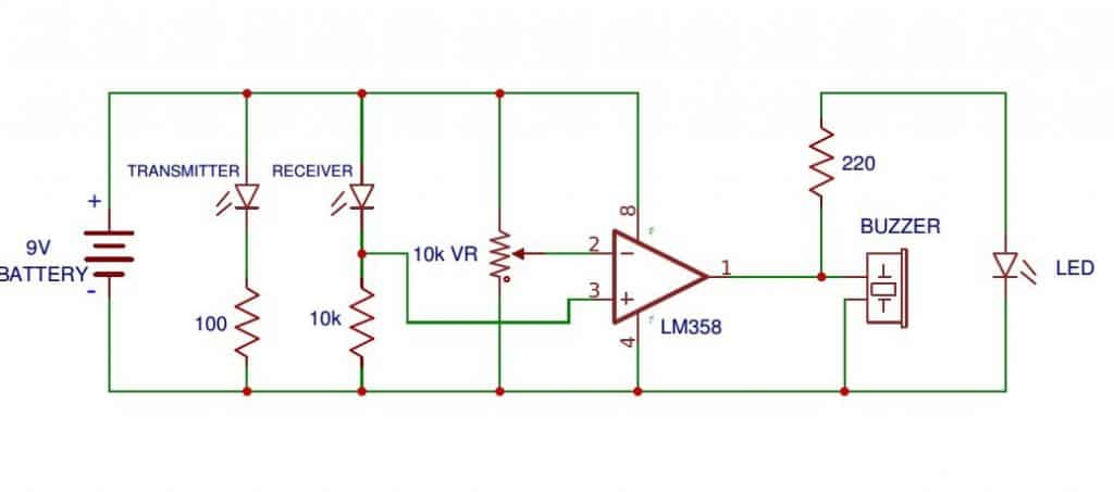
A typical ir sensing circuit is shown below. The 12v dc supply required for the whole circuit can be fed from any standard 12v ac mains adaptorbattery. Based on the intensity of the reception by the ir receiver the output of the sensor is defined. It consists of an ir led a photodiode a potentiometer an ic operational amplifier and an led. Pin1 pin2 and pin3 are corresponded to drain source and ground terminal of the device. Working of the circuit is simple and straight forward.
We uses normal switch in our daily life and after a long time used to these swithing system we can no more interested in that. Obstacle sensing circuit or ir sensor circuit. The passive infrared sensor consists of three pins as shown below. This infrared proximity sensor circuit use 5 volts power supply and consume under 1 milliamp sensor circuit and 50 milliampsir led so its not good if you use a battery as power supply you. Remote controlled switch this is the very simple circuit diagram of ir remote control switch.

