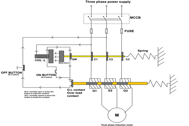
Learn how a capacitor start induction run motor is capable of producing twice as much torque of a split phase motor. Induction motor protection system the circuit diagram of the three phase induction motors is shown in the figure below.

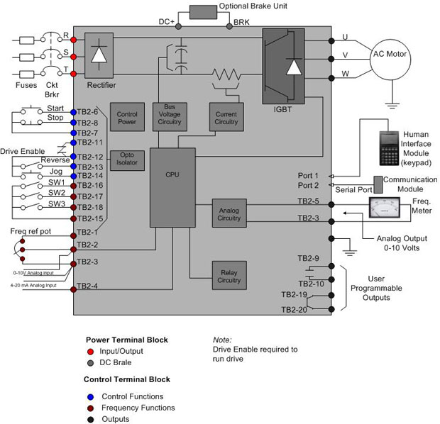
Ac Motor Speed Controller Circuit
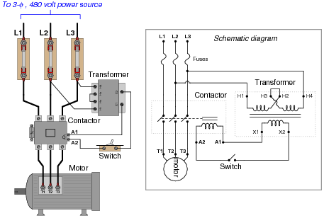
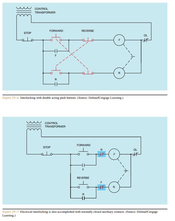
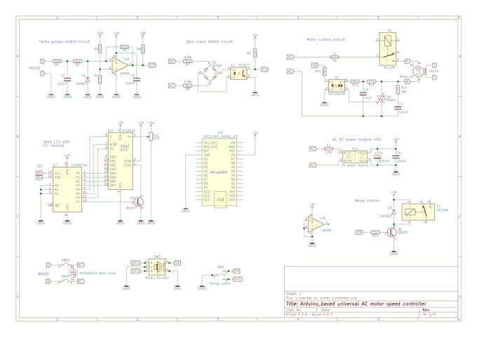
Induction motor control circuit diagram. A very common form of latch circuit is the simple start stop relay circuit used for motor controls whereby a pair of momentary contact pushbutton switches control the operation of an electric motor. See more ideas about electrical diagram electrical circuit diagram electrical engineering. The old post triac based motor speed control if we avoid the pwm control section and power circuit use for just on and off for a low voltage three phase induction motor 100 volt to 150 volt frequently with help of a on off sensorin 100 or more voltagemotor too hot after some time runningif apply 50v three phase it will be working finebut. Also read about the speed torque characteristics of these motors along with its different types. This video gives a brief explanation on how a three phase motor control circuit works. This type of motor requires low starting torque but needs to keep a constant torque while running.
Starting stopping of 3 phase motor from more than one place power control diagrams. Capacitor run induction motors as seen in figures 10 and 11 are much like the capacitor start induction run with the exception of the start winding and run winding stay in the circuit at all times. Speed control of an induction motor there is a various method of speed control of an induction motor. From the equation 1 it is clear that the motor speed can be changed by a change in frequency f a number of poles p and slip s. The rotor speed of an induction motor is given by the equation shown below. Magnetic contactor starter essentially consists of a set of start and stop push buttons with associated contacts overload and underload protective devicesthe start push button is a momentary contact switch that is held normally open by a spring.
The control circuit consists of push button switches auxiliary contacts and a timer. In this particular case i show a low voltage control circuit and a 3 phase higher voltage motor. Three phase motor connection stardelta y δ reverse forward with timer power control diagram. Controlling the interchanging star connection and delta connection of an ac induction motor is achieved by means of a star delta or wye delta control circuit. On off three phase motor connection power control schematic and. Click here to view a capacitor start motor circuit diagram for starting a single phase motor.
Control circuit of star delta starter open transition. Wondering how a capacitor can be used to start a single phase motor. Capacitor run induction motor. Feb 5 2020 explore elects agass board electrical diagram on pinterest. Control 3 phase motor from more than two buttons power control diagrams.


