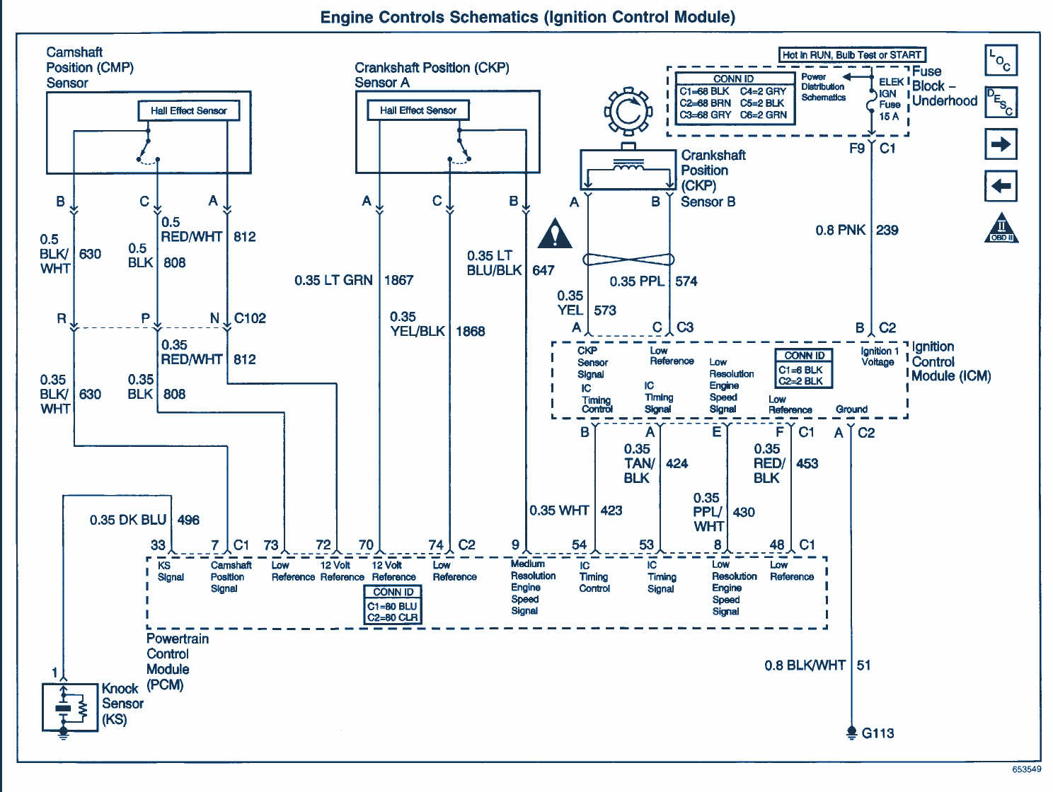
How to test the ford ignition control module. Wiring color codes here is a listing of common color codes for mercury and mariner us made outboard motors.

Mercury Outboard Wiring Diagrams Mastertech Marin
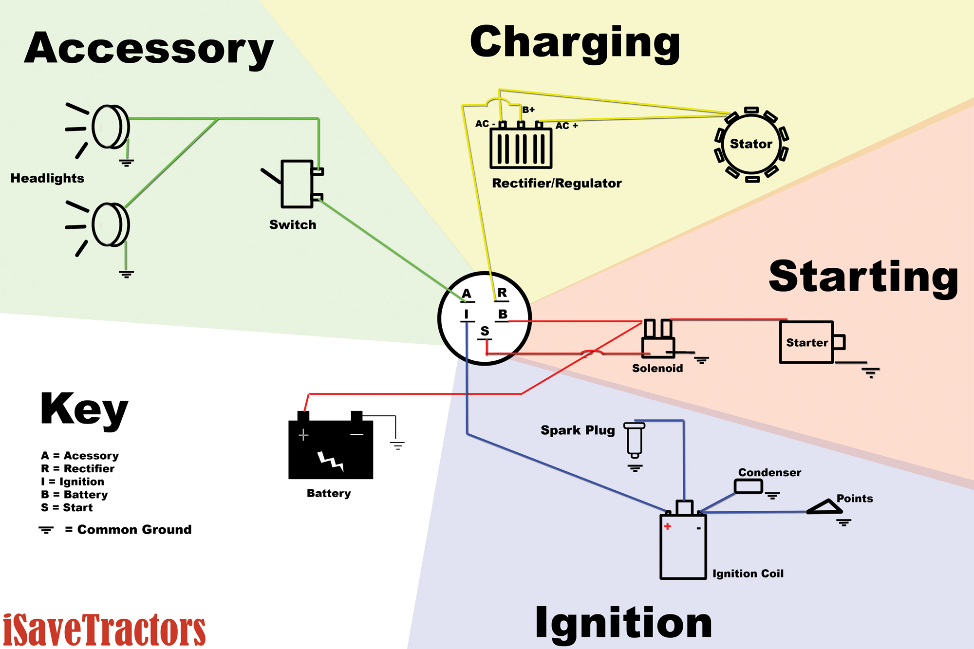
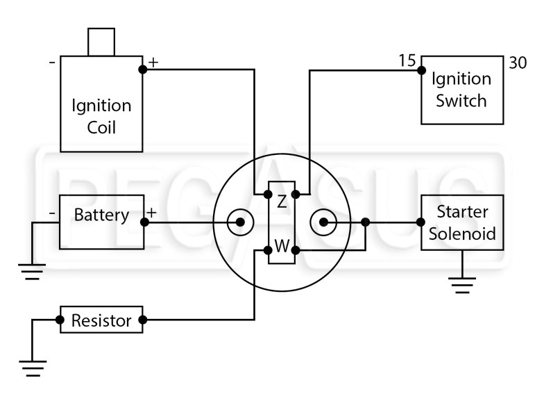
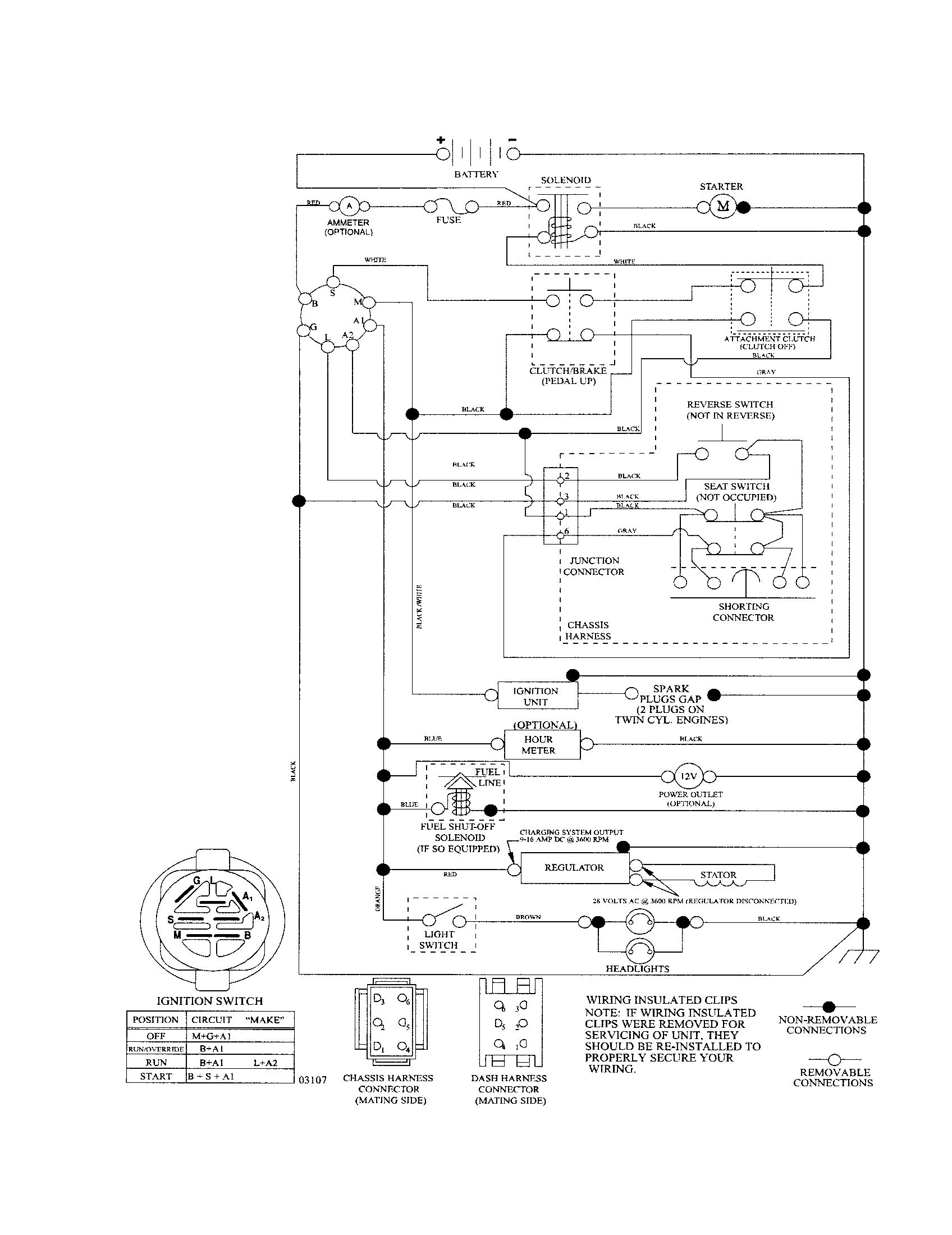
Ignition switch wiring schematic. Lawn mower exmark lazer hp operators manual. The switch positions are acc for accessory r for run s for start and off for off. It shows the parts of the circuit as simplified forms as well as the power and also signal connections between the devices. Riding lawn mower ignition switch wiring diagram download lawn mower ignition switch wiring diagram moreover lawn mower. Attractive cub cadet wiring harness diagram electrical. You can find the ignition control module test explained here.
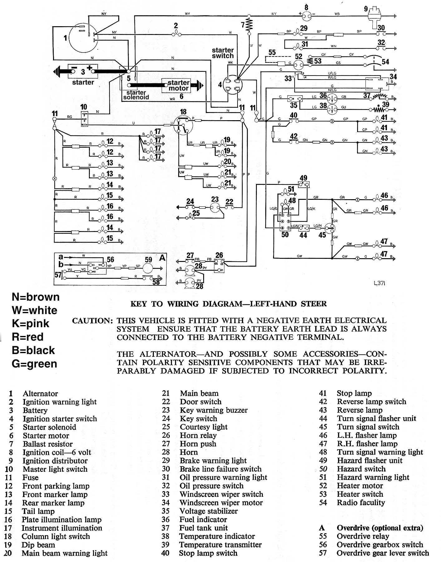
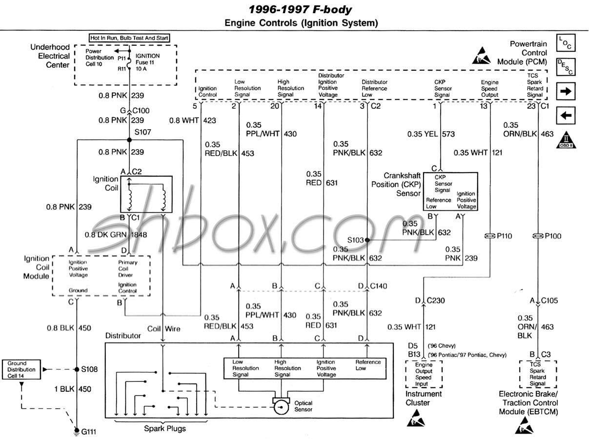
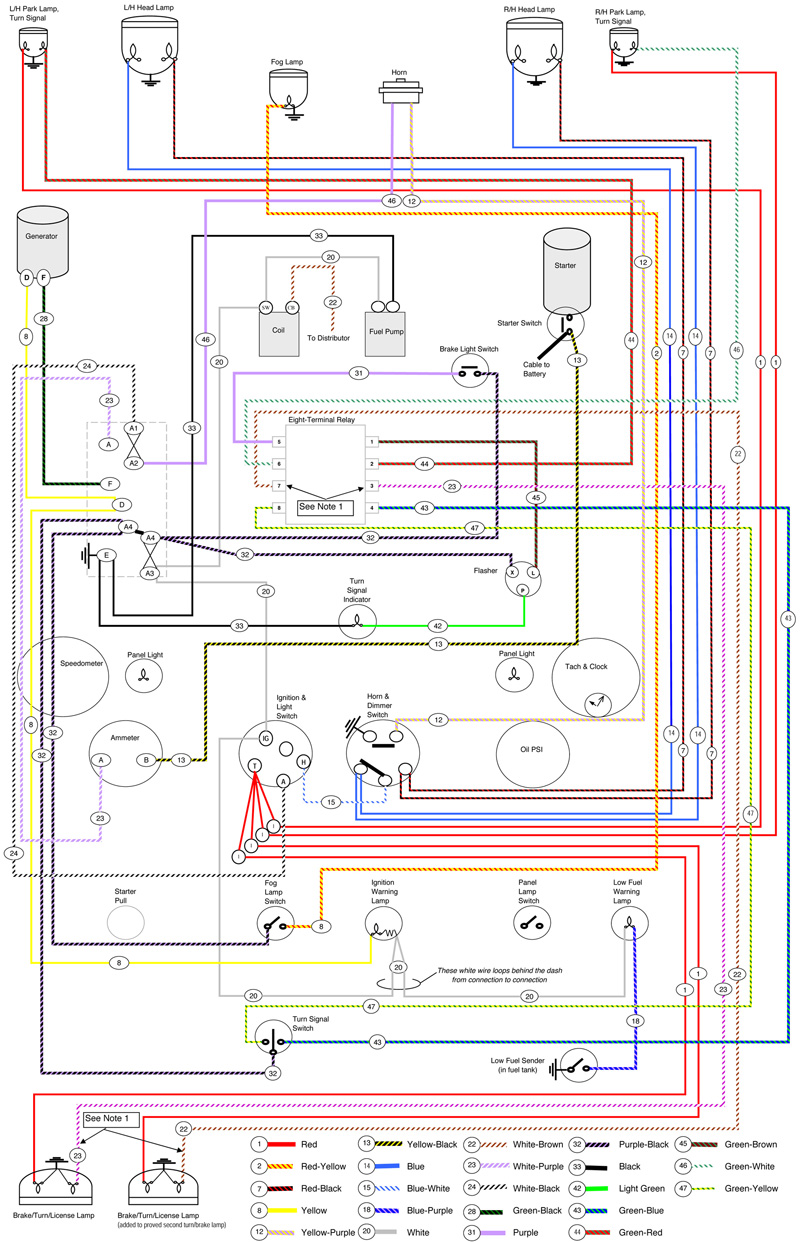
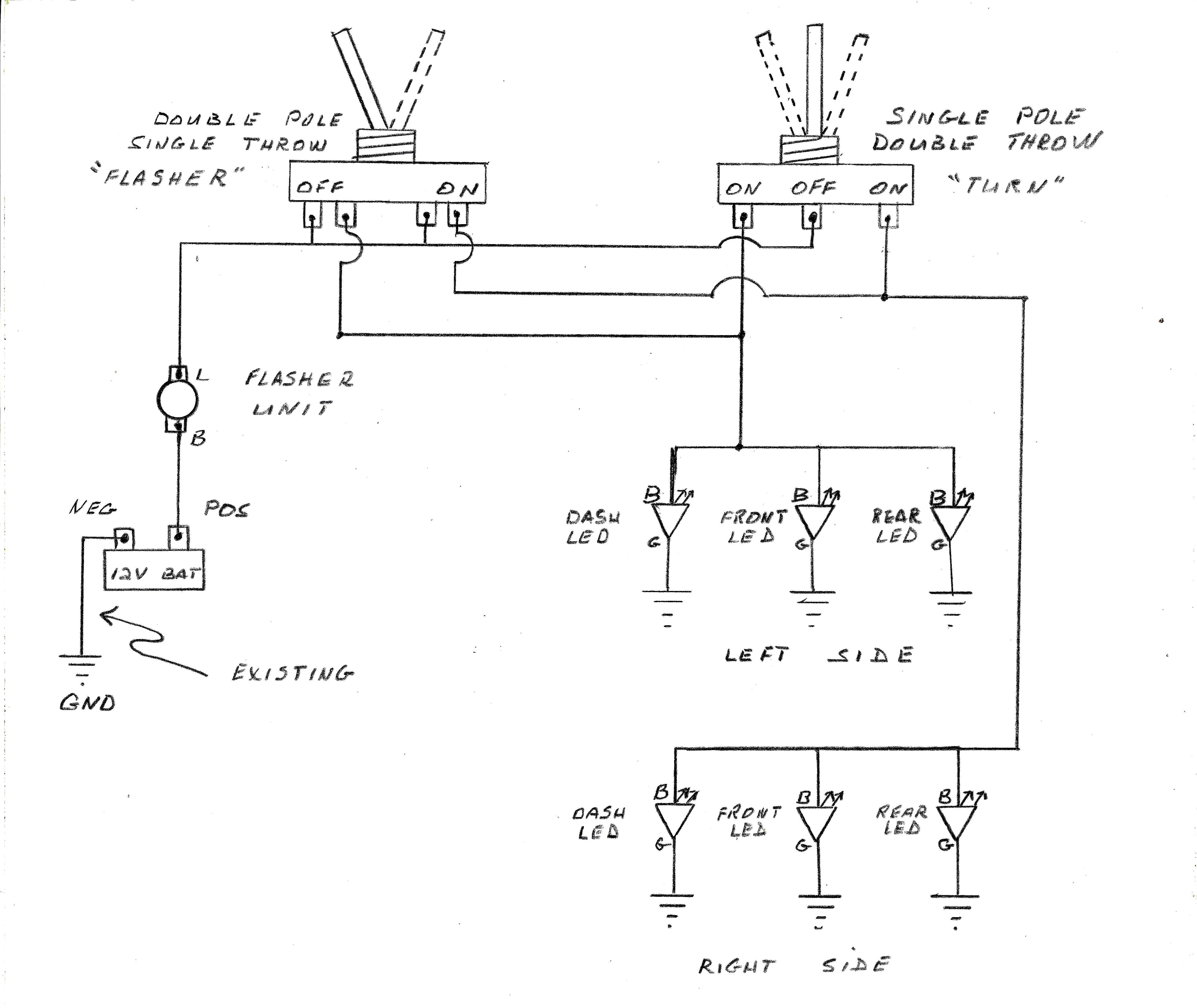
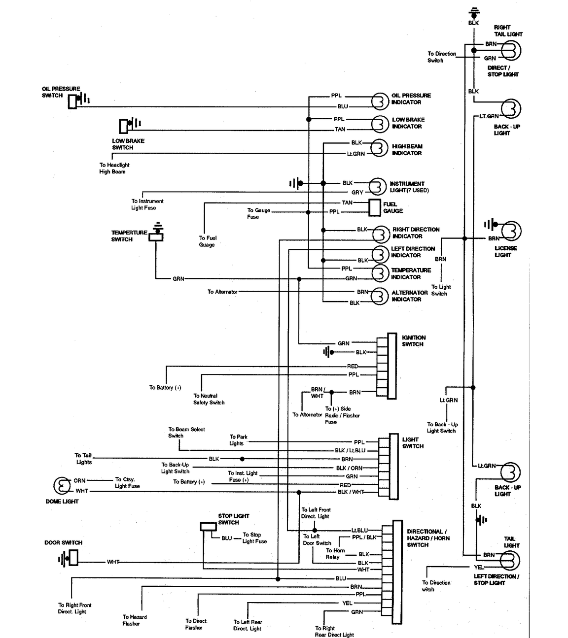
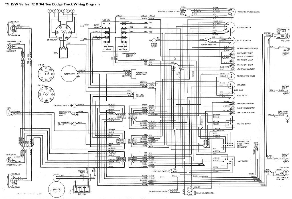
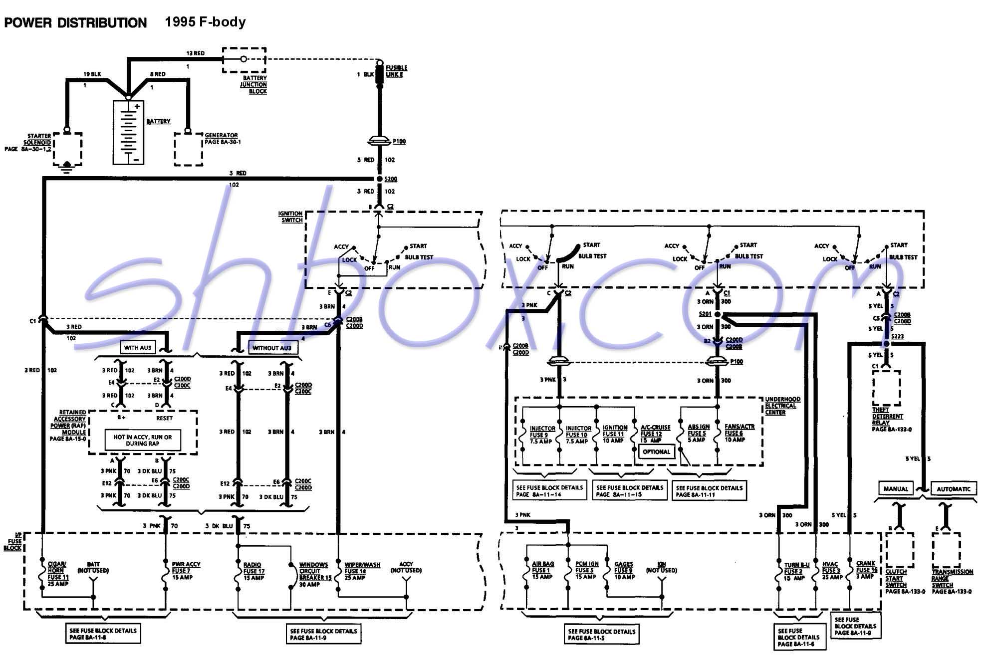
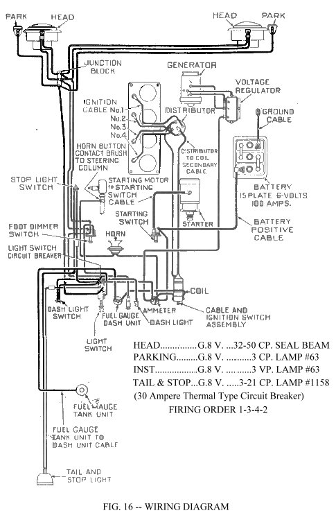
In the next page youll find the icm connectors pinout with a brief description of each wire. A wiring diagram is a streamlined conventional pictorial depiction of an electric circuit. Exactly how is a wiring diagram different from a schematic. You can find the 1994 1995 ignition system wiring diagram here. 15 luxury lawn mower ignition switch wiring diagram. A schematic shows the plan and also feature for an electric circuit yet is not interested in the physical.
Draw a wiring schematic. See how the anti. These codes apply to later model motors approximately early 80s to present. Cub cadet wiring diagram collections of cub cadet 682 wiring diagram collection. Zero turn riding mower operators manual. Cub cadet lt1045 wiring schematic download.
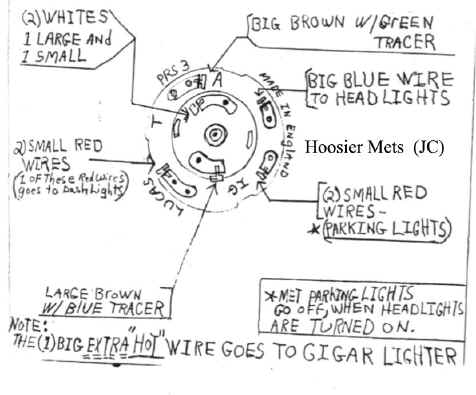
Ford ignition system circuit diagram 1994 1995 49l 50l and 58l. The back of the switch is marked with the function of the switch. Assortment of c4 corvette wiring diagram. Ignition switch wiring diagram cub cadet refrence briggs and. This is critical for a successful job. Lawn and garden equipment exmark lazer z air cooled series operators manualfind great deals on ebay for exmark lazer z ignition switch.
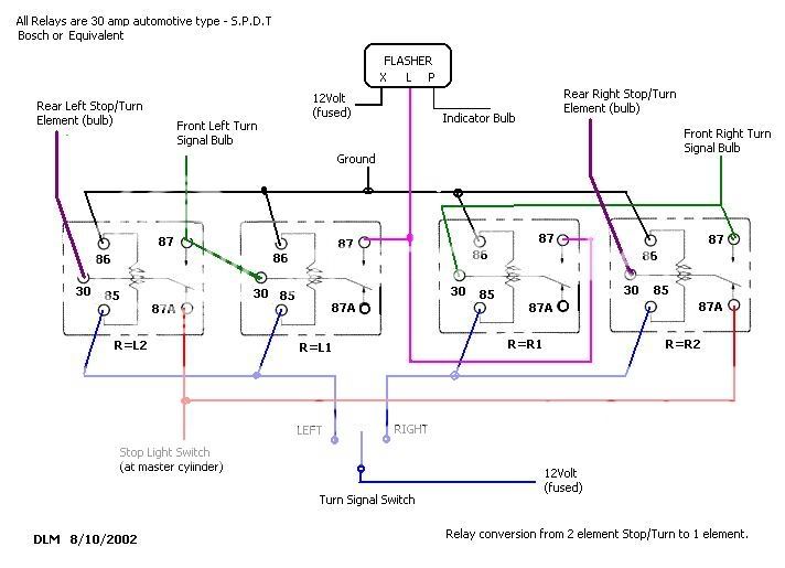
Plan each circuit carefully and include circuit protection either inline fuses or a fuse panel in the diagram. Learn to navigate this systems wiring circuitry and diagram using current flow analysis relay and module operation and neutral switch actuation such as circuit completion.
