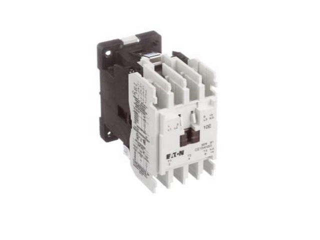
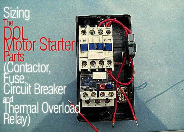
Pdf contactor wiring diagram with timer. Otherwise the arrangement wont function as it.

Iec Standard Contactors
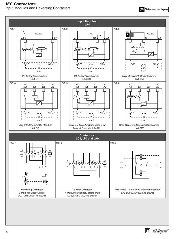
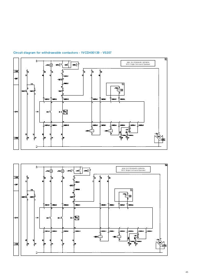
Iec contactor wiring diagram. Dol motor starter with 230v contactor coil. The following tables describe the device and show the symbol by area of usage. Our bulletin 100s safety contactors provide safe isolation of hazardous motion loads using mirror contact performance. How to wire a contactor and overload. Looking for dayton 120vac iec magnetic contactor. You must watch this video.
Easy online ordering for the ones who get it done along with 247 customer service free technical support more. Lighting contactor wiring diagram with cell westmagazine net. Contactor wiring diagram pdf download furnas contactor wiring diagram download. Iec contactor wiring diagram bureaucraticallyfo. Magnetic contactor circuit diagram luxury thermal overload relay. The purpose of this document is to provide a simple cross reference of common schematicwiring diagram symbols used throughout various parts of the world.
4 table 2 nema and iec terminal markings. Iec contactor wiring diagram bureaucraticallyfo. Of poles 3 32 full load amps inductive 2uxl6. Cross reference mz081001en effective november 2013. Nice manual motor starter wiring diagram frieze electrical circuit. Iec motor starter wiring diagram download 44 best motor starter circuit diagram.
Our bulletin 100s104s iec safety contactors provide mechanically linked or mirror contact performance up to 750 a which are required in feedback circuits for modern safety applications. Xt iec contactors are suitable for global use and cover the entire output range from mini contactor relays up to 7 a all the way to vacuum contactors up to 3180 a. Iec contactor specifications bulletin numbers 100104 k 100104 c 100104s c 100104 e 100s e 100104 d 100s d 100 g 100q c topic page product line overview 3 iec contactors 3 safety contactors 4 100 k104 k miniature contactors 5 product selection 5 accessories 10 specifications 13 life load curves 17 approximate dimensions 19. The xt iec contactors are powerful efficient and versatile and can be combined with our full range of electronic overload relays and bimetal relays. How to wire a contactor and motor protection switch. Wiring diagram book a1 15 b1 b2 16 18 b3 a2 b1 b3 15 supply voltage 16 18 l m h 2 levels b2 l1 f u 1 460 v f u 2 l2 l3 gnd h1 h3 h2 h4 f u 3 x1a f u 4 f u 5 x2a r power on optional x1 x2115 v 230 v h1 h3 h2 h4.
Use transformer if you need to. The diagram symbols in table 1 are used by square d and where applicable conform to nema national electrical manufacturers a ssociation. Contactor breakers limit switch no static control. Wiring a single phase motor through a 3 phase contactor how and why. Contactor breakers limit switch no static control standard elementary diagram. Graingers got your back.
Typical controller markings typical elementary diagram iec typical.

