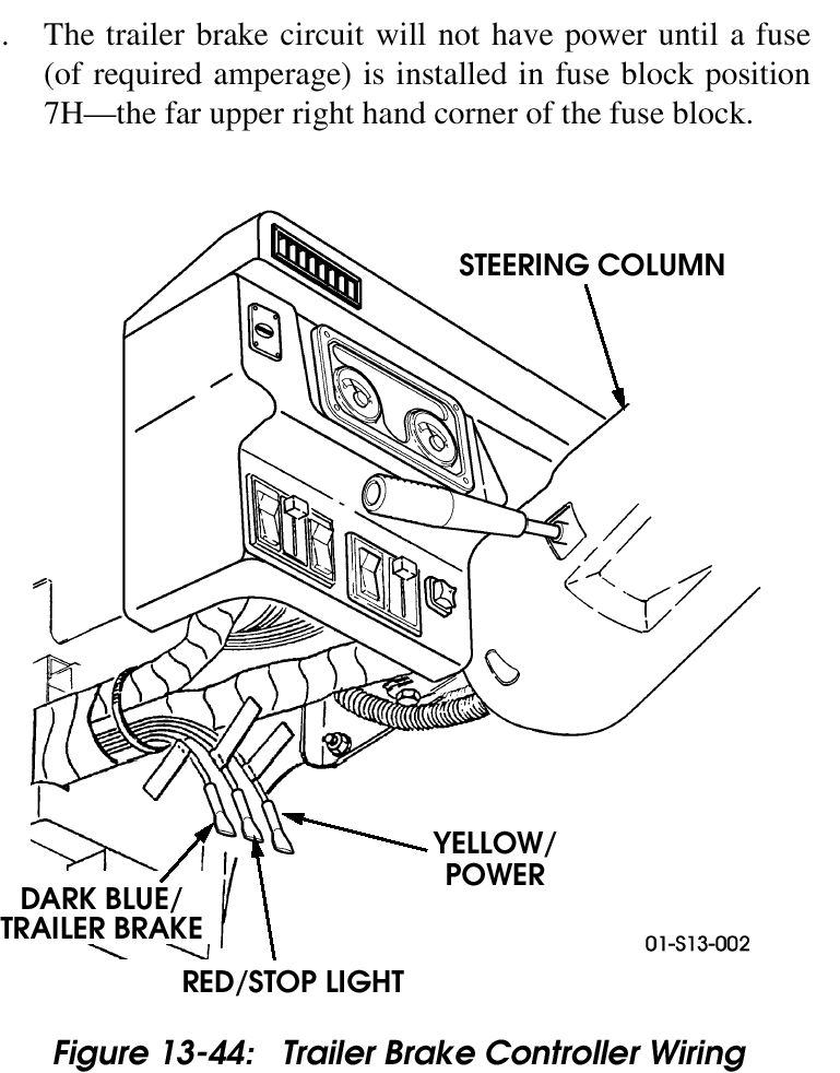
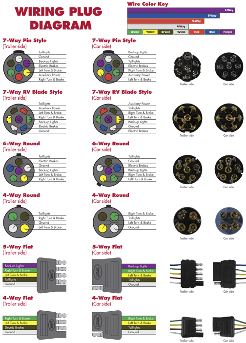
Hopkins 7 blade trailer wiring diagram wiring diagram is a simplified all right pictorial representation of an electrical circuitit shows the components of the circuit as simplified shapes and the gift and signal friends in the middle of the devices. Change the way you protect your trailer investments with the engager trailer break away system.
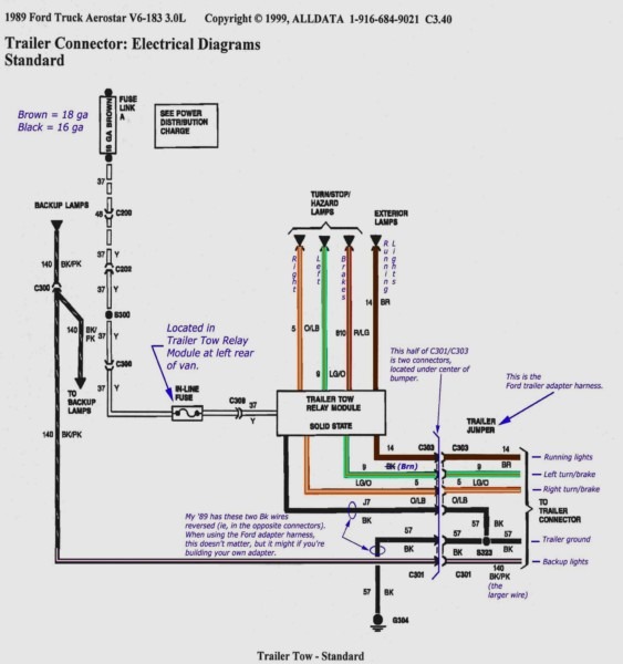
Impulse Trailer Brake Wiring Diagram C3 Wiring Diagram
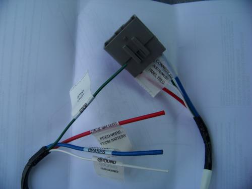
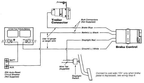
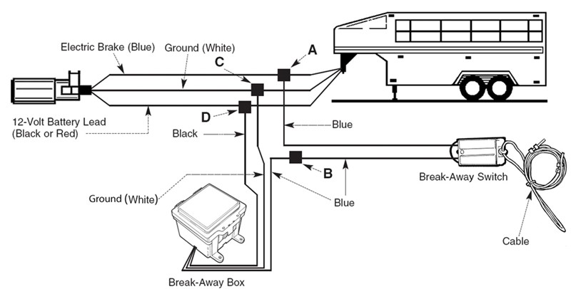
Hopkins trailer brake wiring diagram. Reduce brake controller installation time. Trailer breakaway wiring diagram 3 wire trailer breakaway switch wiring diagram hopkins trailer breakaway wiring diagram rv trailer breakaway switch wiring diagram people today understand that trailer is a vehicle comprised of quite complicated mechanics. This car is designed not just to travel one place to another but also to take heavy loads. Connect the second wire coming out of the switch to the brake wire blue coming out of the battery. Connect other blue wire of break away switch to the blue wire labeled brake from the break away box b. The two wires coming out of the breakaway switch into the trailer brake wire running from the trailer connector to the brakes.
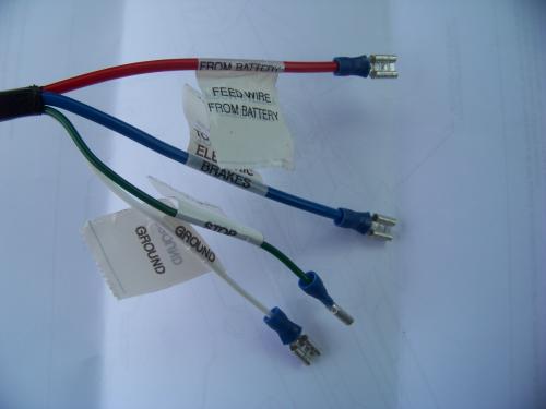
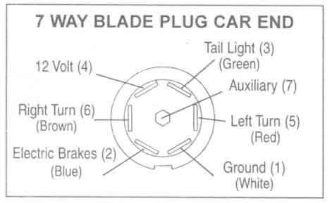
Color coding is not standard among all manufacturers. See point a on the wiring diagram. Details hopkins tekonsha with and without a charger. Whether you are replacing the trailer connector or rewiring the entire trailer find the hopkins trailer wiring solution for you. Identify the wires on your vehicle and trailer by function only. Splice one blue wire of the break away switch to the electric brake wire coming from the trailer side connector a see diagram on next page.
Wire the breakaway kit. Hopkins brake controllers turn technology into confidence. Every hopkins brake control is backed with a lifetime warranty for complete customer confidence. For any vehicle with start stop technology we recommend using our 47297 insight 47294 or 47295 agility brake controls with advanced proportional braking. Refer to product instructions and locate wires on vehicle by function only.

