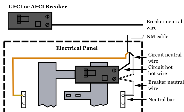
15amp 20amp 30amp and 50amp as well as a gfci breaker and an isolated ground circuit. Typically one panel feeds the entire house but there can also be another smaller panel called a subpanel which may be used to serve a specific area such as an addition a large kitchen or a detached garage.
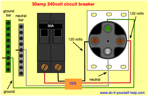
Circuit Breaker Wiring Diagrams Do It Yourself Help Com
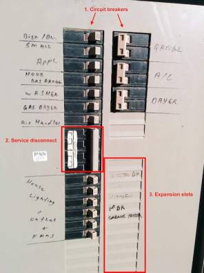
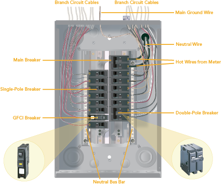
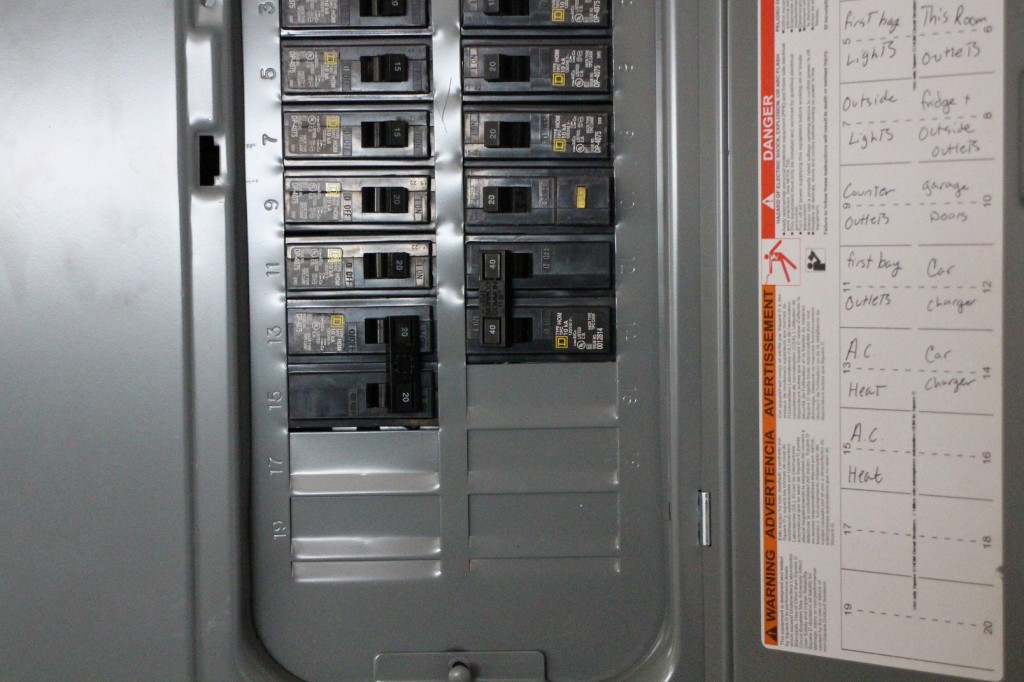
Home circuit breaker panel diagram. This diagram illustrates some of the most common circuits found in a typical 200 amp circuit breaker service panel box. Numbers should correspond to each circuit breaker. Though the following instructions refer to circuit breakers the same procedure applies to panels that utilize fuses. Make a list that you can post on the inside of the door. This page contains wiring diagrams for a service panel breaker box and circuit breakers including. Wiring a breaker box is a highly technical skillknowing how it operates isnt.
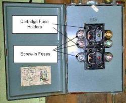
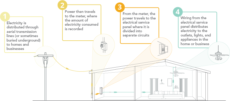
This diagram compares a main panel as i have diagrammed it so far with how a typical panel is arranged. This overview assumes that the electrical panel is installed on the wall of a utility area near where the main feeder wires come into the home and that all branch circuit wiring cables and conduit runs are already installed. With the door open you can access all the circuit breakers in the panel. In a new home construction or a rewiring project the last step will be connecting all the wires to the circuit breaker box which is what this article describes. A service panel is a steel box with a hinged door or lift up panel on the front. The breaker or fuse will interrupt the current the flow if it ever starts to approach a dangerous level.
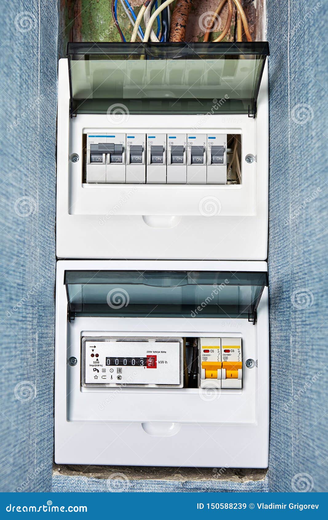
Circuit breaker panel box wiring diagram. Take some of the mystery out of those wires and switches that lurk behind the door of your breaker box with this. If the circuit breakers arent already numbered inside the electrical panel number them. There may be in the panel a distinct main breaker that can shut off power to most or all the circuits.
