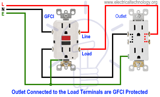
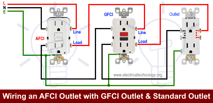
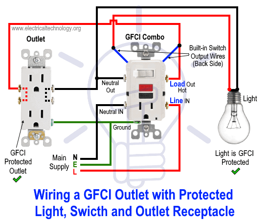
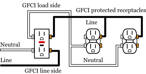
In this special case wiring diagram both light and ordinary outlet is connected to the load terminals of gfci. So gfci designed as checking the difference between the current leaving and returning through current transformer of the gfci to protect device exceeds 5ma.

A Light Wiring Diagram For Gfi Wiring Diagram
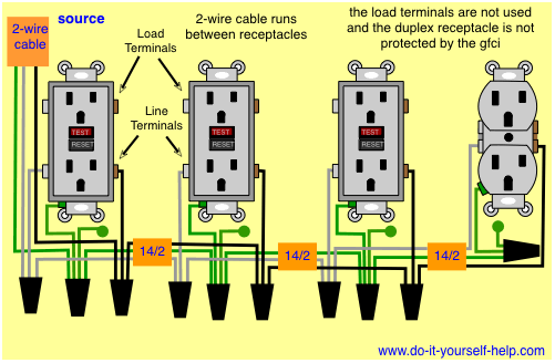
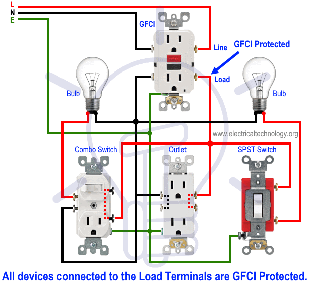
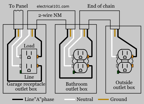
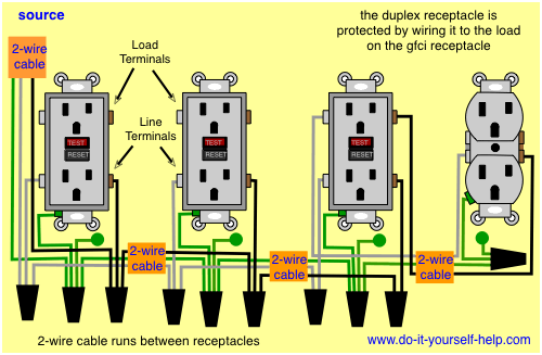
Gfci receptacle diagram. In the gfci mainly two wires connect as also shown in a diagram the current flowing from the source and coming back are some due to current laws. This diagram illustrates the wiring for multiple ground fault circuit interrupter receptacles with an unprotected duplex receptacle at the end of the circuit. Wiring a gfci combo switchoutlet with protected light outlet receptacle. In this gfci outlet wiring and installation diagram the combo switch outlet spst single way switch and ordinary outlet is connected to the load side of gfci. Wiring a gfci receptacle is a little more complicated than hooking up a regular outlet but easily learned once explained. If you are replacing an existing gfci outlet with a new one we suggest that you read our page about replacing a gfci outlet.
How to wire gfci outlets. The light onoff operation can be controlled through the gfci switch while the ordinary outlet is directly connected to the gfci load terminals. Gfci outlet wiring diagram. It means all the connected loads to the load terminals of gfci are protected. It reveals the parts of the circuit as simplified forms as well as the power and signal links in between the tools. Wiring a gfci outlet with combo switch outlet receptacle light switch.
Variety of leviton gfci receptacle wiring diagram. You can also learn about wiring gfci outlets in the following 7 steps. The load terminals on the gfci are not used and the last receptacle is wired directly to the circuit source. Gfci receptacle in a series with an unprotected outlet. A wiring diagram is a streamlined traditional photographic depiction of an electric circuit.
