This video shows drawings to aid with city and guilds and eal electrical exams at level 1 2 3 5357. The following will affect the value of earth fault loop impedance.

Earth Fault Loop Impedance Test Jim S Test And Tag
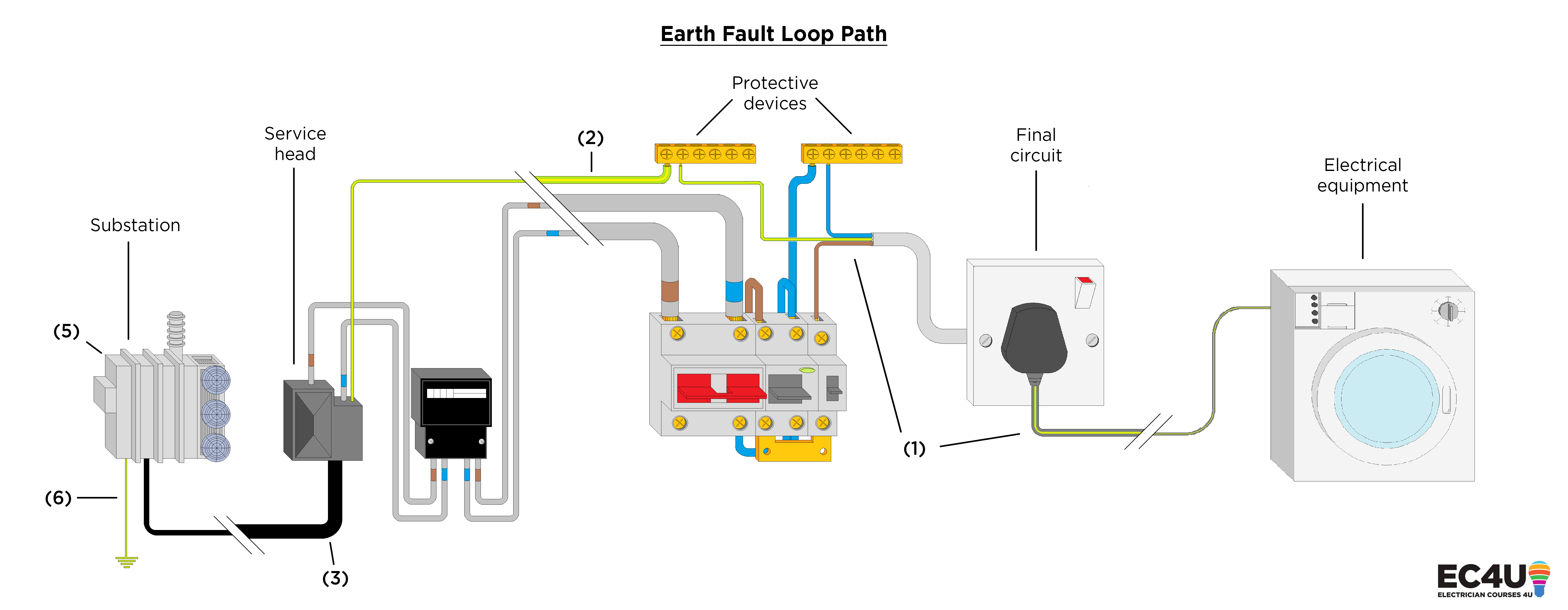
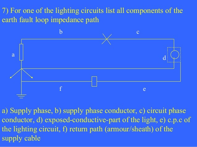
Earth fault loop path diagram for a lighting circuit. So the circuit must correctly meet the efli criterea. For example on a tn s system how do i show how the earthing conductor connects onto the lead sheath. Reply to earth fault loop impedance test for lighting circuits in the periodic inspection reporting certification area at. Mar 15 2020 13. Im in need of a circuit diagram of the earth fault loop impedance path from eg. The circuit breaker curve describe how value of fault current affects the time of its opening during fault condition.
R1 is the resistance of circuit phase conductor and r2 is the resistance of circuit earth conductor ze is the external supply impedance of earth fault current path loop to earth zs is the total impedance of earth fault current path loop to earth. I have done a tt system but not sure how to show on paper how the earths connect together using correct symbols. Earth fault loop impedance is the path followed by fault current when a low impedance fault occurs between the phase conductor and earth ie. For each final circuit and distribution circuit it must be confirmed that the value of line earth loop impedance zs is low enough to achieve automatic disconnection of supply to the circuit within the relevant maximum time specified in regulation group 41132 in the event of an earth fault. Earth fault loop impedance zs 100 or 80 values on site with matt. Gsh electrical 8167 views.
Distribution equipment including. Calculations using bs 7671 duration. Diagram for earth fault loop path for a lighting circuit in the uk. What affects efl impedance. Where ze is derived from a high current test and r1 r2 obtained during continuity testing of the circuits. Lighting 26351 apply lighting filter.
This guide considers the measurement and calculation of the prospective short circuit current and prospective earth fault current at the origin and at other relevant points in the installation. Because of this the iec provide a specific values of earth fault loop impedance to maintain the integrity of our protective devices. The higher the impedance the lower the fault current will be and the longer it will take for the circuit protection. Zs earth fault loop impedance of the circuit tested ze earth fault loop impedance external to the supply r1r2 sum of the resistance of line and earth for the tested circuit. Earth fault loop impedance path for an installation connected to a tn s earthing arrangement. A faulty kettle for a tn s earthing system and tn c s.
Fault current is driven round the loop by the supply voltage. The circuit should be designed so that an mcbfuse will disconnect the supply in the event of an earth fault.


