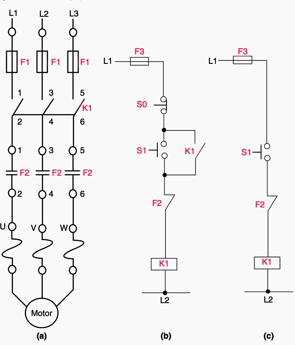
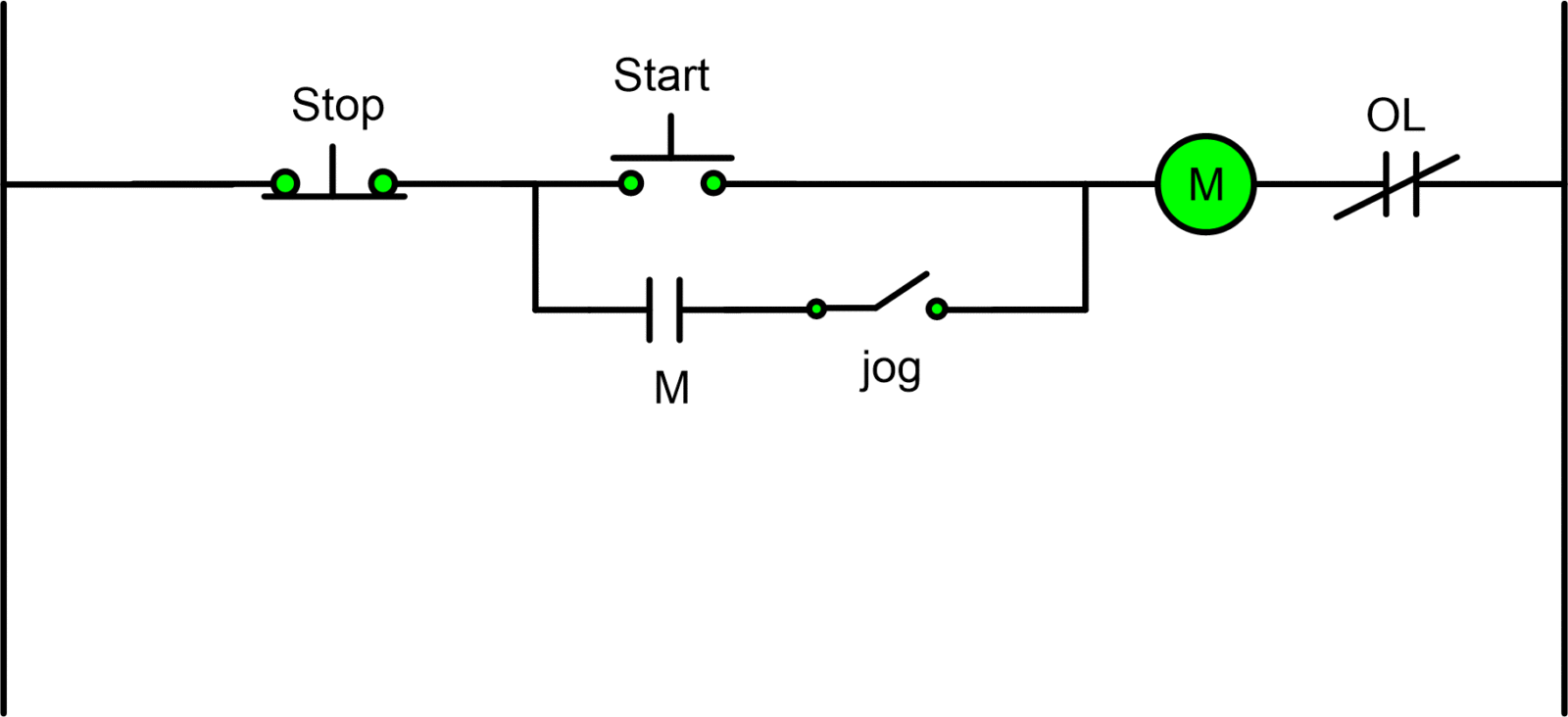
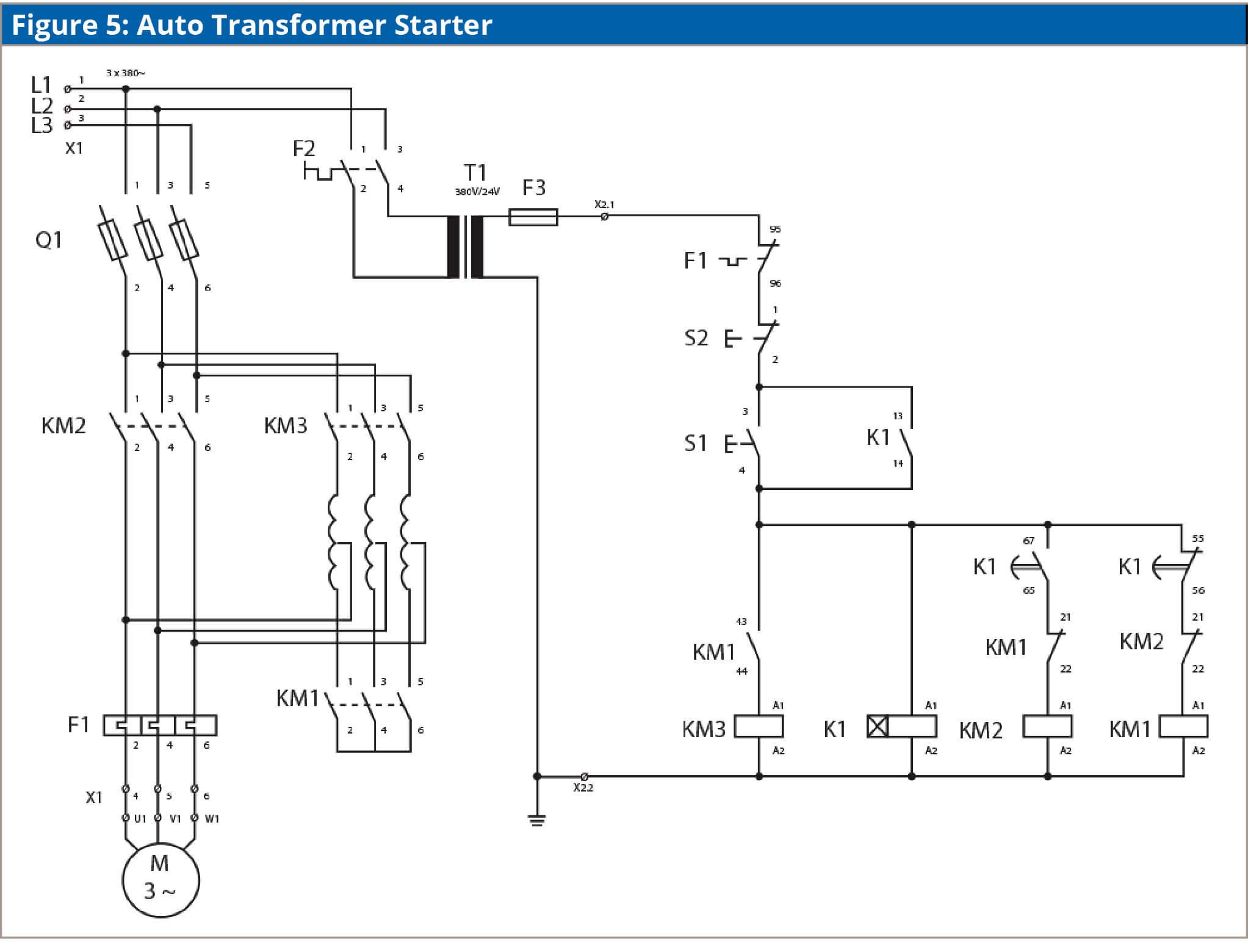
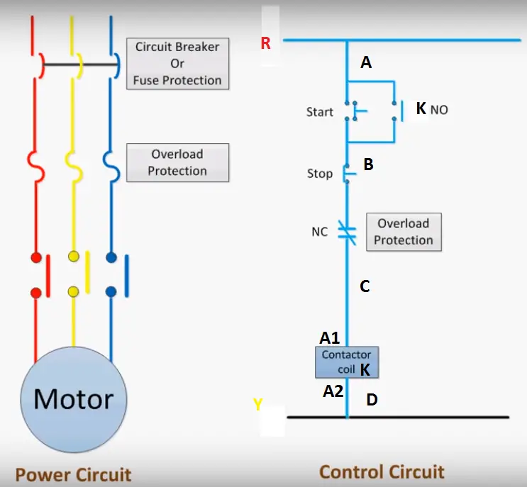
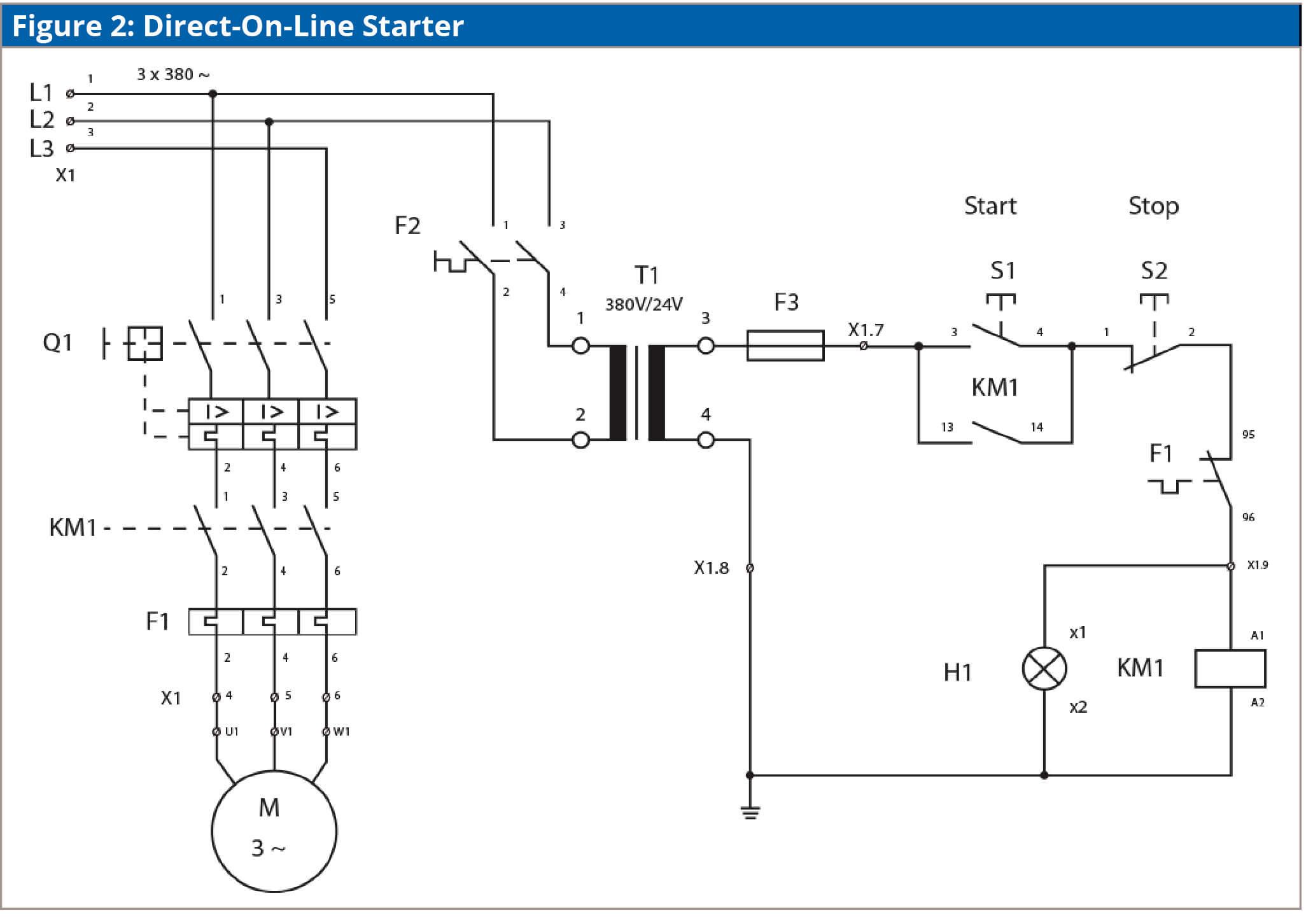
I dol starter wiring connection with start and stop buttons are shown in the above figure 1. A dol starter is a direct on line motor starter.

Dol Starter Motor Wiring Diagram Diagram Base Website Wiring
Dol starter motor connection diagram. All connection i shown with complete guide. Capacitor connection diagram of ceiling fan video. Note that the single phase dol starter wiring diagram is also like this. A dol motor starter contains protection devices and in some cases condition monitoring. The dol starter joints the 3 phase main wiring with the induction motor namely l1 l2 and l3 when the start switch is pressed. 3 phase motor contactor wiring diagram.
Sometimes known as an across the line starter this type of motor controller is used as a simple starter for larger electric motors providing. The direct on line motor starter dol consist a mccb or circuit breaker contactor and an overload relay for protection. The 3 phase dol starter wiring diagram is shown below. A wiring diagram of a dol starter is. Despite this direct connection no harm is done to the motor. Troubleshooting a motor starter.
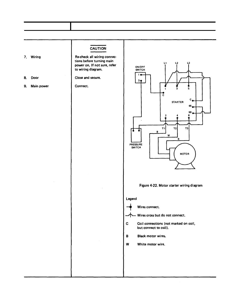
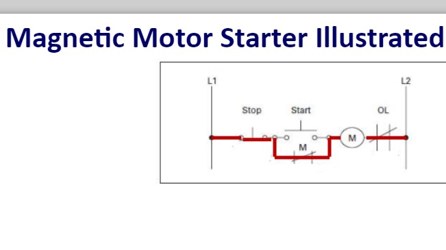
In the above three phase dol starter wiring diagram. Water pump controller with float switch. How dol starter control diagram works when we press the start button to start the motor the relay gets the phase and circuit completed thus coil energizes and contactors produce magnetic field the main contactor closes and motor gets the supply and the motor startswhen we press the stop button the circuit will interrupt and the motor stop. In which the three phase induction motor connection shown and all the direct online starter wiring shown with simple steps. In the below dol starter wiring diagram i shown a molded case circuit breaker a magnetic contactor normally open push button normally close push button switch thermal overload relay motor trip indicator and 3 phase motor. The thermal overload is supplied as a separate item.
In dol starter an induction motor is connected directly across its 3 phase supply and the dol starter applies the full line voltage to the motor terminals. 3 phase dol starter control and power wiring diagram. Electromagnetic contactor which can be opened by the thermal overload relay under fault conditions. Generally the direct online starter working can be done in two different stages namely dol starter control circuit and dol starter power circuit. Direct on line dol motor starter description the direct on line motor starter dol is designed to switch a single or three phase induction motor at rated voltage. The simplest form of motor starter for the induction motor is the direct on line starter.
Then read the below article and learn from simple dol starter wiring diagram. Between the mains supply terminals and motor terminals the dol starter main terminals are connected and with the two terminals of the three phase power supply as described in figure 1 the control circuit is energized. It comprises an enclosure in steel or plastic a contactor start contact link wires and stop start buttons.
