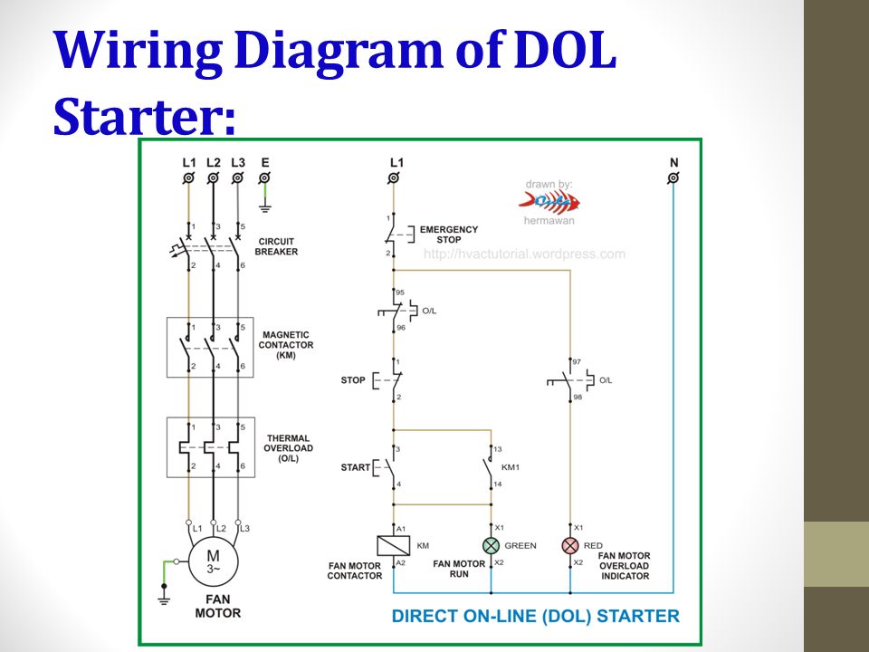
The l1 contactor is connected from normally open no to r phase using mccb. In three phase dol starter wiring the two types of wiring done.

Dol Starter Control Wiring Diagram Pdf Bmw 18
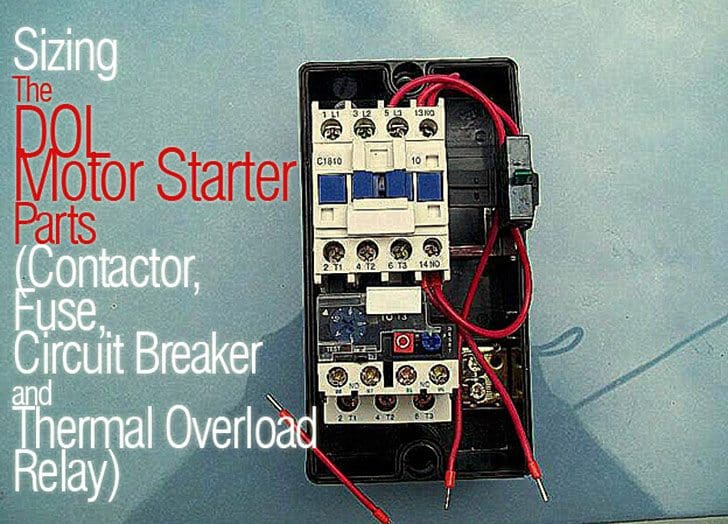
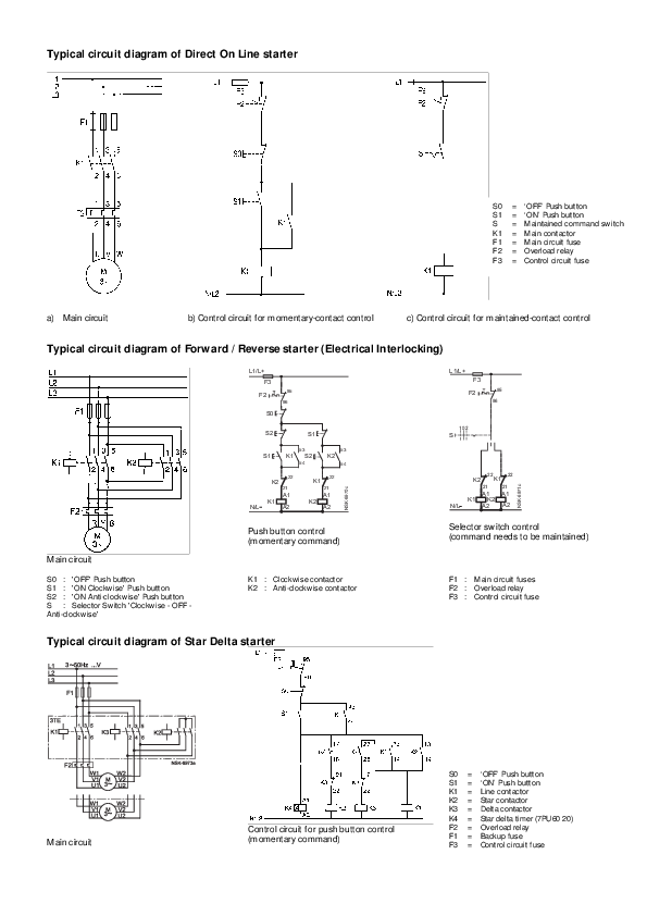
Dol starter control circuit diagram pdf. Posted on march 27 2019 by admin. Dol starter working principle. The connection of contactor can be done among relay coil supply voltage as well as thermal overload. Direct on line dol motor starter 3 wiring of dol devices for 230v single phase with 230v coil wiring of additional start stop devices on dol devices for 400v 3 phase with 230v coil additional start and stop stations can be wired to the dol control circuit. It shows the parts of the circuit as simplified shapes and also the power and also signal links in between the tools. Dol starter control circuit diagram consist components like main power contactor start button stop push button and overload relay is connected in series this circuit is called control circuit of dol motor starter.
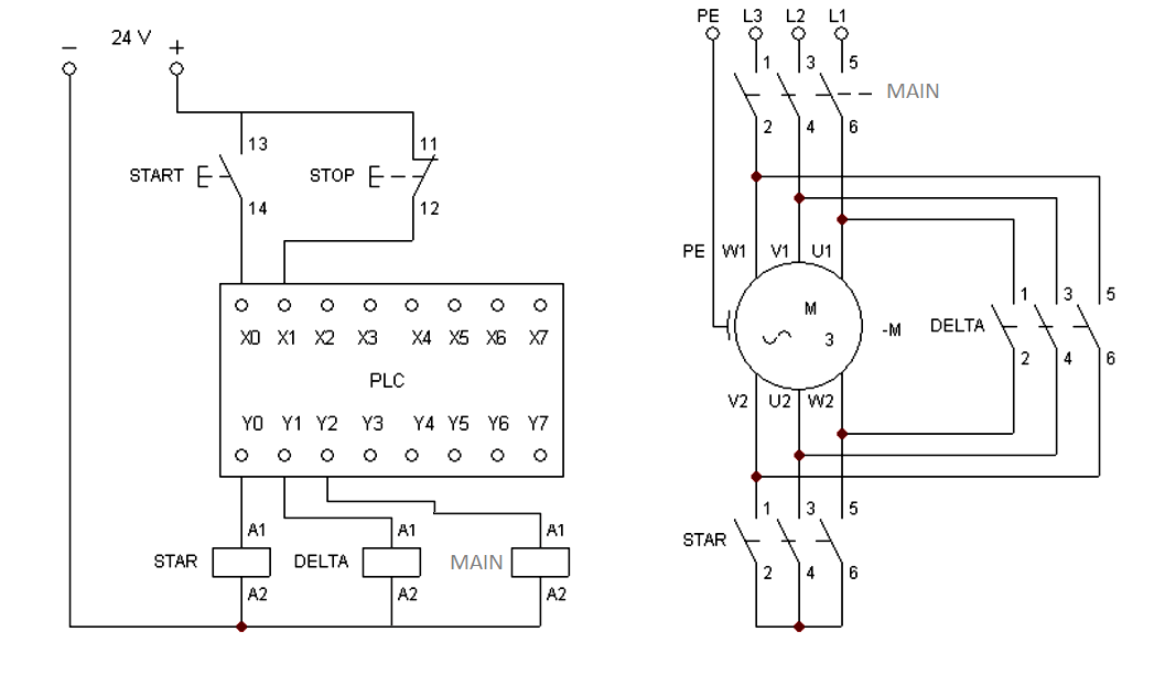
Click on the image to enlarge and then save it to your computer by right clicking on the image. The wiring of direct on line control circuit starter is following. In the below dol starter wiring diagram i shown a molded case circuit breaker a magnetic contactor normally open push button normally close push button switch thermal overload. Dol starter control diagram three phase. The control circuit is connected to any two phases and energized from them only. Assortment of 3 phase motor starter wiring diagram pdf.
When we push stop button control circuit of starter will be break at stop button and supply of relay coil is broken plunger moves and close contact of main contactor becomes open supply of motor is disconnected. And one wiring is called controlling wiring. In this post we are going to know the details of each part of dol starter diagramall parts of the dol starter power circuit diagram and control circuit diagram are explaineddirect online starter or dol starter is very useful and commonly used ac starterdol starters are mainly used with up to 5 hp motors. In overload condition of motor will be stopped by intermission of control circuit at point 96 95. A wiring diagram is a streamlined conventional photographic representation of an electrical circuit. In principle the start buttons should be momentary normally open device and wired in.
The working principle of a dol starter begins with the connection to the 3 phase main with the motor. Motor starter wiring diagram pdf motor starter wiring diagram pdf dol power circuit. All controlling of starter are controlled by this circuit. Control circuit diagram of dol starter pdf. One wiring called main wiring which is used for motor. When we press the start button the current flows through contactor coil magnetizing coil and control circuit also.
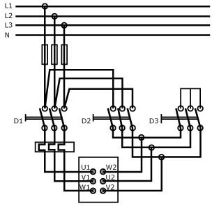
Dol starter wiring diagram pdf new valid industrial motor control control circuit of semi automatic star delta starter pdf dol starter control wiring diagram with timer pdf popular star delta animation drawing the schematic diagram of autotransformer starter dol. Wiring diagram pics detail. Variety of motor starter wiring diagram pdf.

