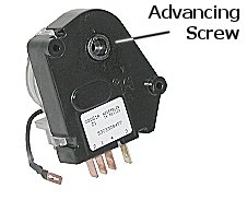
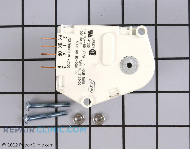
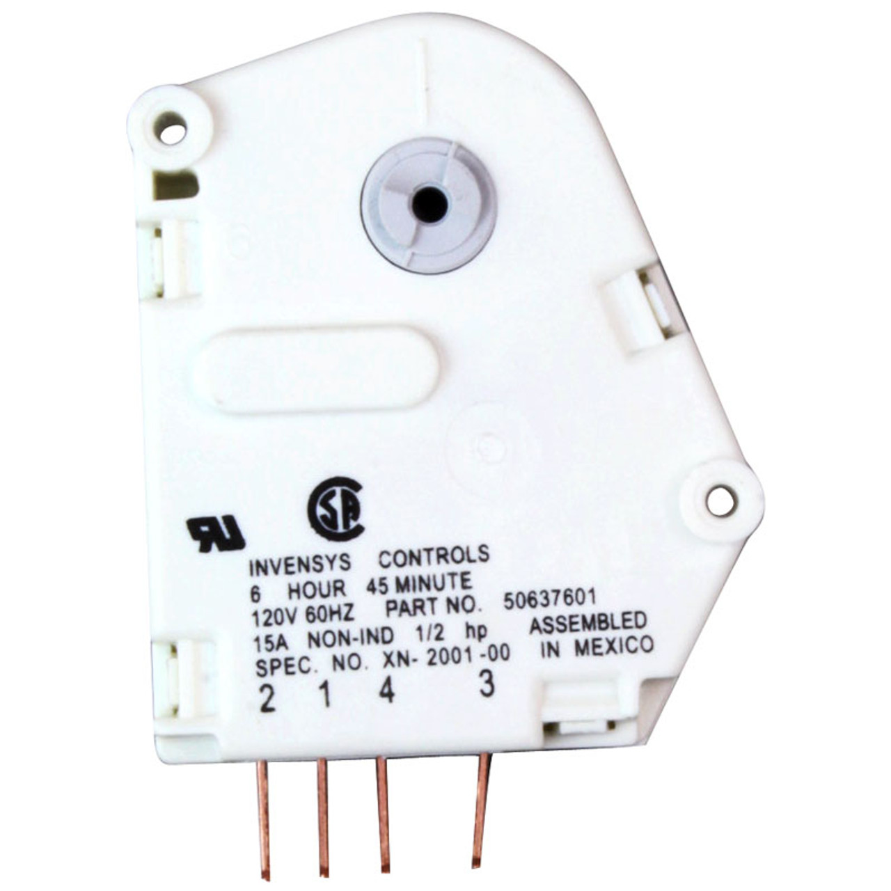
Ac service tech llc 154990 views. Timer construction the defrost timer is operated by a single phase synchronous motor like those used to operate electric wall clocks figure 281.

8fcf Ge Electric Dryer Timer Switch Wiring Diagram Wiring
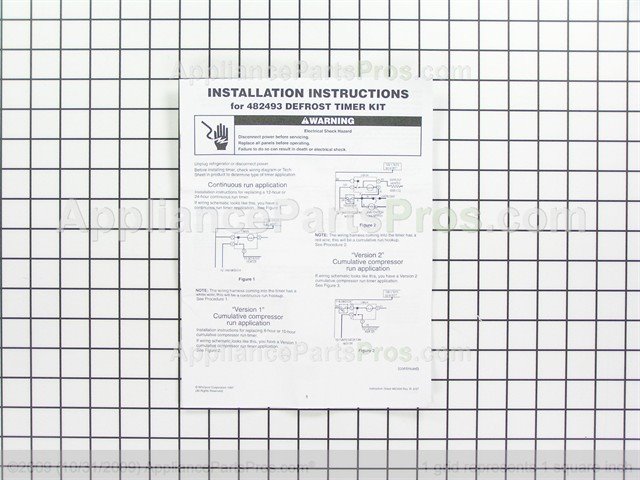
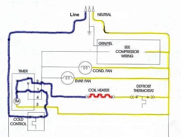
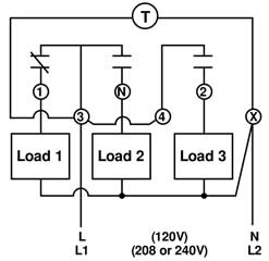
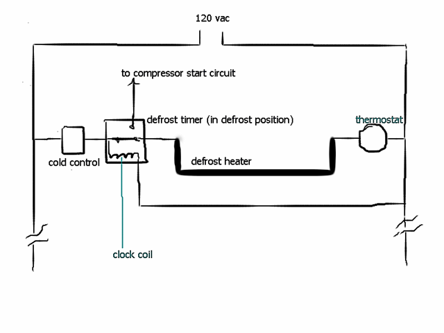
Defrost timer wiring schematic. Wiring diagram images detail name walk in freezer defrost timer wiring diagram refrigerator defrost timer wiring diagram download paragon time clock wiring diagram lukaszmira best timer defrost file type source metroroomph size 337 71 kb dimension x variety of walk in freezer defrost timer wiring diagram click. A schematic drawing of the timer is shown in figure 282. Walk in freezer defrost timer wiring diagram wiring diagram is a simplified suitable pictorial representation of an electrical circuitit shows the components of the circuit as simplified shapes and the skill and signal associates together with the devices. Icons that represent the components in the circuit and also lines that represent the connections between them. When the defrost timer is in defrost mode you should measure an open circuit between pin 1 main power input and pin 4. Collection of paragon defrost timer 8145 20 wiring diagram.
Whirlpool defrost timers only. Once the 10 hours is over the defrost timer will switch back to pin 2 activating the defrost. A wiring diagram is a sort of schematic which makes use of abstract pictorial symbols to reveal all the interconnections of elements in a system. Whirlpool tech line gave me an easy way out. Wiring diagrams are made up of two points. This timer kit is designed for both.
Test the defrost timer. Walk in freezer defrost timer wiring diagram free wiring. Kenmore refrigerator defrost timer w this eight hour defrost timer so i figured my model was too old the wiring diagram was simalar to mine on. A wiring diagram is a simplified traditional photographic depiction of an electrical circuit. The contacts are operated by a cam that is gear driven by the clock motor. Refrigerator compressor not running.
Test the start relay overload capacitor ptc thermistor duration. When i was a little unsure about hooking those defrost timers up where the timer motor wire went 1 terminal or 2 terminal. You can test a defrost timer by measuring the resistance in the circuits when the timer is in each mode. If the timer has a white wire going to it the timer lead goes on 1 anything else goes on 2. It reveals the elements of the circuit as streamlined shapes and also the power as well as signal links in between the tools.
