On the automatic mode motor a has to run for 3 minute then motor b comes on also. The electromagnet that holds the starter in the run position is in the field circuit.

8deb3e 12 Volt Dc Motor Starter Wiring Diagram Wiring Library
Dc motor starter circuit diagram. The only drawback or limitation of the four point starter is that it cannot control the speed of the high current in the motor. Dc motor speed control circuits 12 32 volts 30 amps of power can operate with speed control pwm technique is. Wiring diagrams show the connections to the controller. The 4 point starter has a lot of constructional and functional similarity to a 3 point starter but this special device has an additional point and coil in its construction as the name suggests. On the manual mode motor a and motor b can be controlled separately by selector switch. The self excited motors are further classified as shunt wound or shunt motor series wound or series motor and compound wound or compound motor.
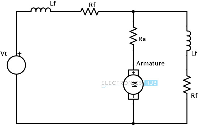
Complete circuit diagram for the motor controller along with the parts list has been included here. Types of dc motor a direct current motor dc is named according to the connection of the field winding with the armaturemainly there are two types of dc motors. First one is separately excited dc motor and self excited dc motor. Can you help me with the controlled diagram. This starter is a so called three point starter. High power 30a dc motor speed control circuit pwm lm358 cd4093.
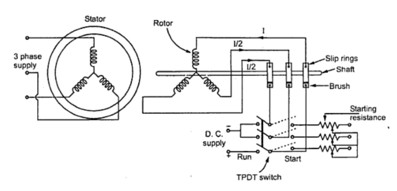
Working principle of 4 point starter. Now the question is why these types of dc motors require the assistance of the starter in the first place. The power circuit connects the line to the motor. This type of starter can be used for shunt and compound motors and if the field is lost the starter drops out protecting the motor against runaway. Three point manual dc motor starter circuit diagram. The speed is controlled through an externally applied varying dc voltage source.
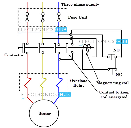
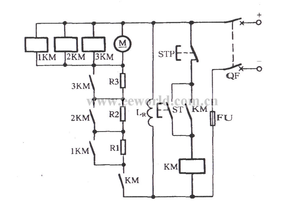
The motor current is carried by the power main contacts of the contactor. 555 timer circuits motor control circuit power electronic projects. When the motor winding is opened under the working condition then the field current usually decreases to zero. A 4 point starter protects the armature of a dc shunt motor or compound wound dc motor against the initially high starting current of the dc motor. 4 point starter circuit diagram drawbacks of 4 point starter. The most striking feature of this circuit is its ability to provide full torque even at minimum motor speeds.
The schematic diagram of the. A 3 point starter is a device that helps in the starting and running of a dc shunt motor or compound wound dc motor similar to a 4 point starter. This is the other motor starter circuit which operates the contactor to turn it on or off. Basic wiring for motor control technical data. It provides transmission of electricity through the starter contacts overload relay and then to the motor. Wiring diagrams sometimes called main or construction diagrams show the actual connection points for the wires to the components and terminals of the controller.
Well its due to the presence of back emf e b which plays a critical role in governing the operation of the motor.
