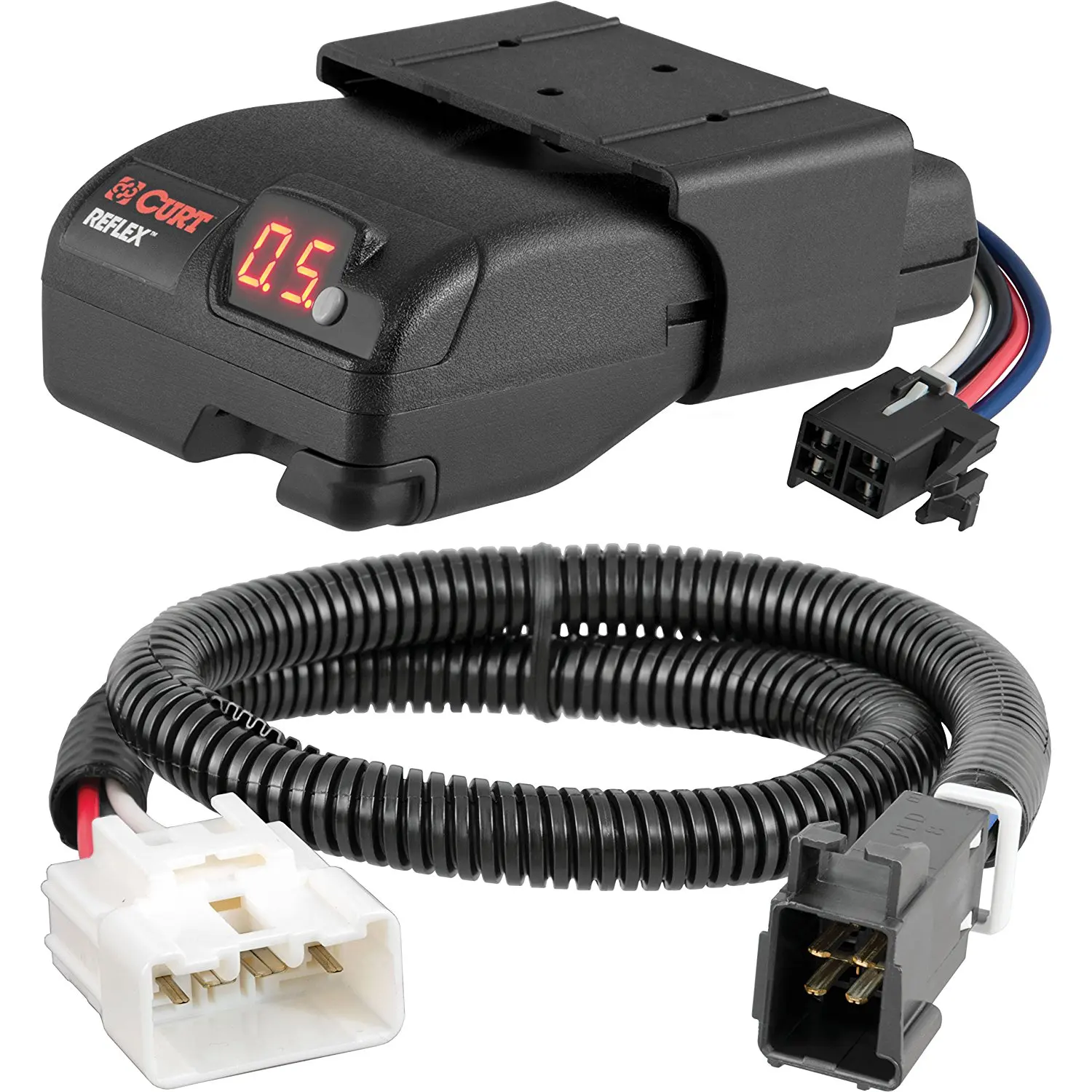
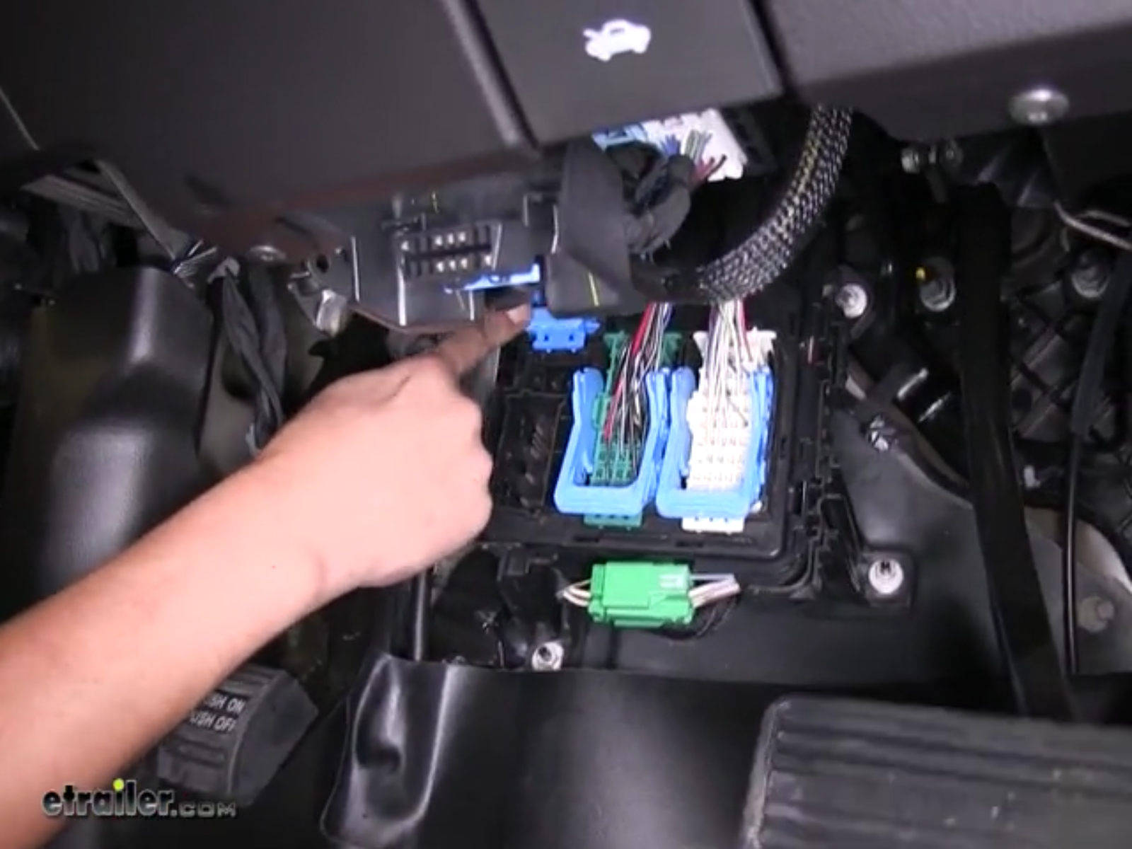
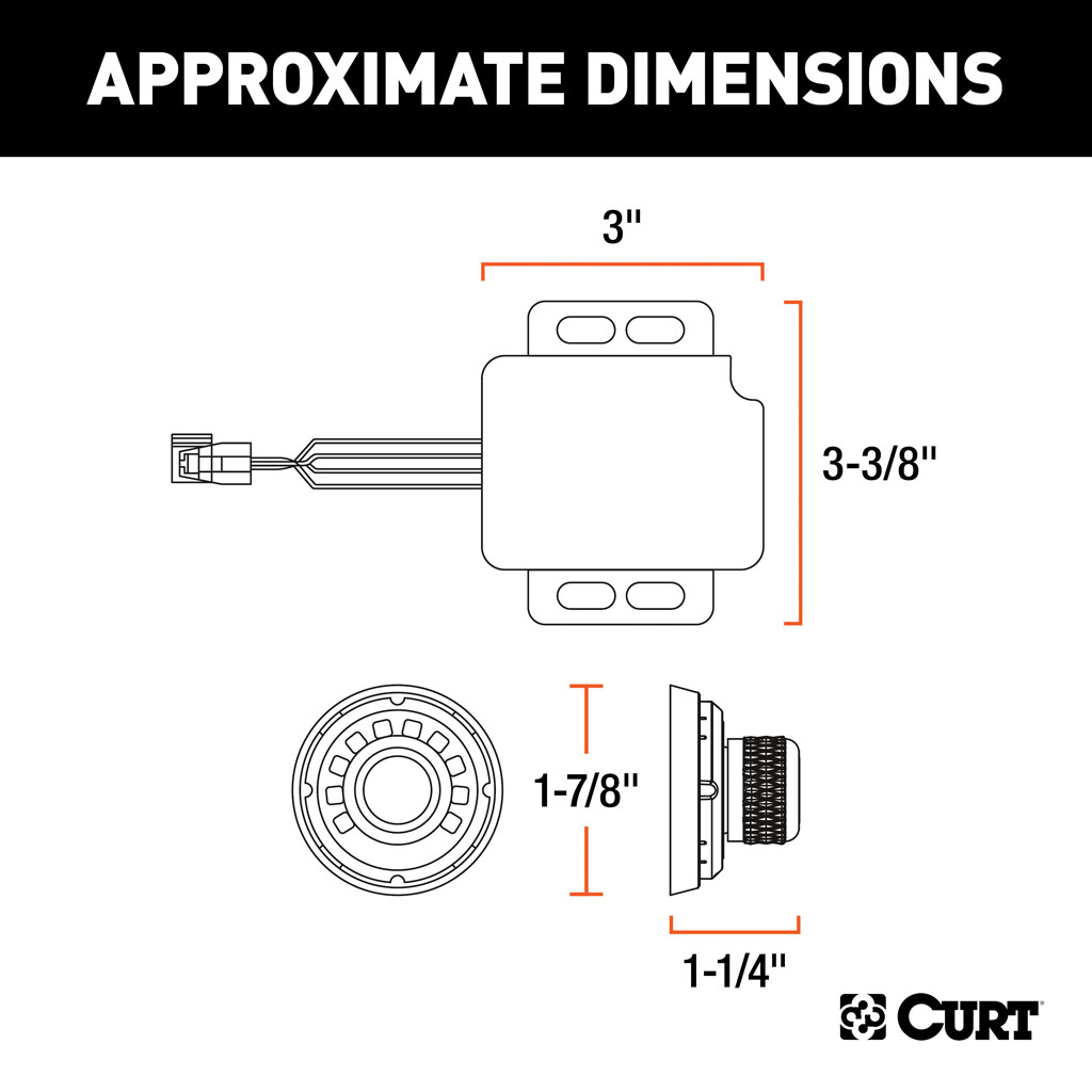
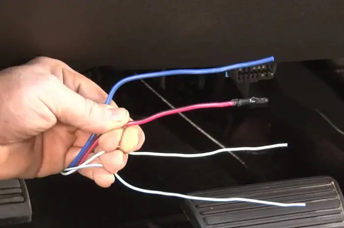
A curt trailer brake control module is available for any job or budget. Installing a brake controller involves disconnecting the vehicle battery mounting the brake controller onto dash and plugging the unit in with a vehicle specific wiring harness.
Wiring Trailer Lights And Brakes Nest Light Bulbs Wiring
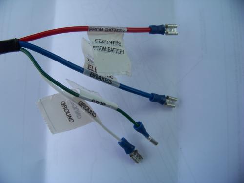
Curt brake controller wiring diagram. To use the curt echo wireless trailer brake controller c51180 your vehicle only needs 12 volt ground and turn signals connected to its 7 way socket. For example if you used a 4 to 7 way adapter such as 30717 there will not be an output wire from the echo to connect to so you could simply tie that wire off as you can. If your vehicle is not equipped with a plug and play harness you can also splice in wiring for connecting a brake controller. In this guide we cover step by step how to install a brake controller. We carry time based and inertia options including our smartphone compatible echo and oem style integrated spectrum. It reveals the components of the circuit as simplified shapes and the power as well as signal connections in between the devices.
Wiring layouts are made up of 2 things. What this means is you do not need the brake signal from the 7 way. Collection of curt brake controller wiring diagram. Curt brake controller c review video install curt venturer trailer brake. Signs that stand for the elements in the circuit and lines that stand for the connections between them. Each curt trailer brake module installs with no splicing needed.
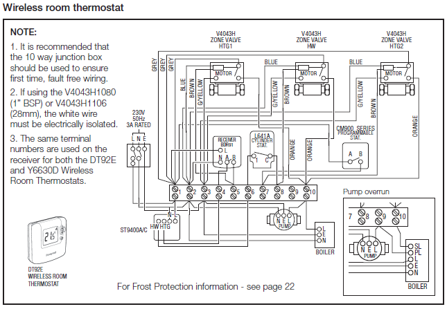
Curt brake controller wiring diagram whats wiring diagram. A wiring diagram is a kind of schematic which uses abstract photographic signs to reveal all the affiliations of elements in a system. Curt brake controller c review review and installation instructions. The above diagram shows the controls and components of the curt venturer. A wiring diagram is a streamlined conventional photographic depiction of an electric circuit.


