The bek3 controller is able to work from 5 up to 36vdc. Overload relay 1ct m m motor 3ct to 120 v separate control ot is a switch that opens.

Following Wiring Diagrams Youtube
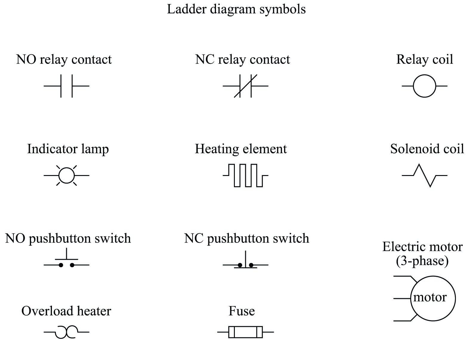
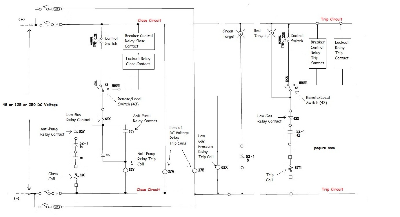
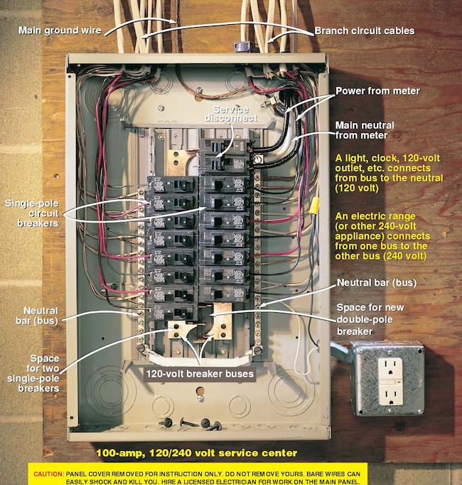
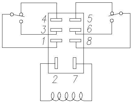
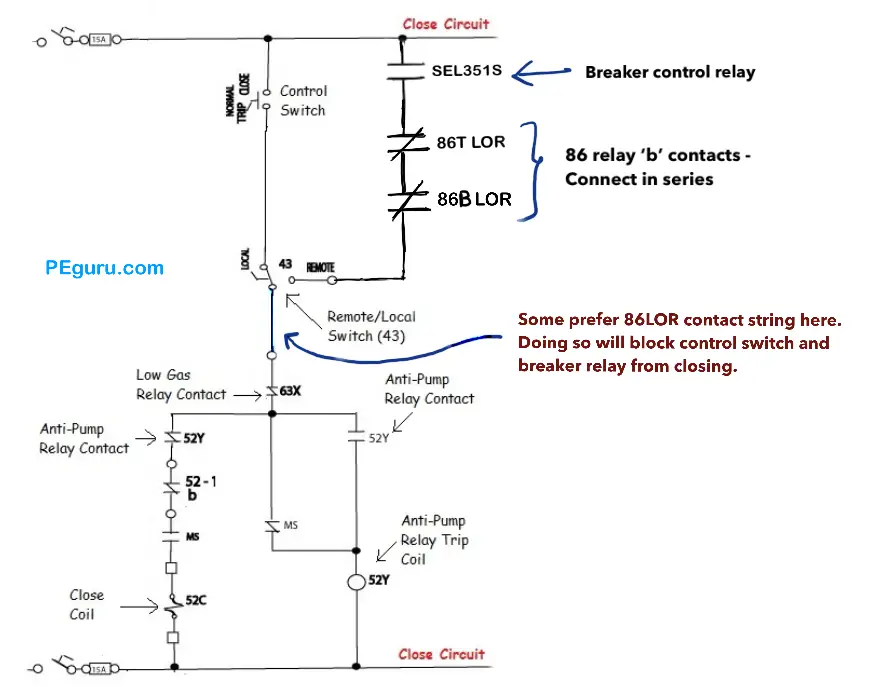
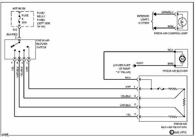
Control and relay panel wiring diagram pdf. Motor control panel wiring diagram pdf wiring diagram is a simplified within acceptable limits pictorial representation of an electrical circuitit shows the components of the circuit as simplified shapes and the aptitude and signal associates in the middle of the devices. No static control standard elementary diagram symbols. Reserves the right to make changes in the products described in this manual. Relay module wiring diagram. To ensure that the switch con tacts are in their correct state modules must be made to communicate with the panel before connecting circuits controlled by t he mod ule. Each area may be controlled independently and each room can be segregated by zone for customizable control.
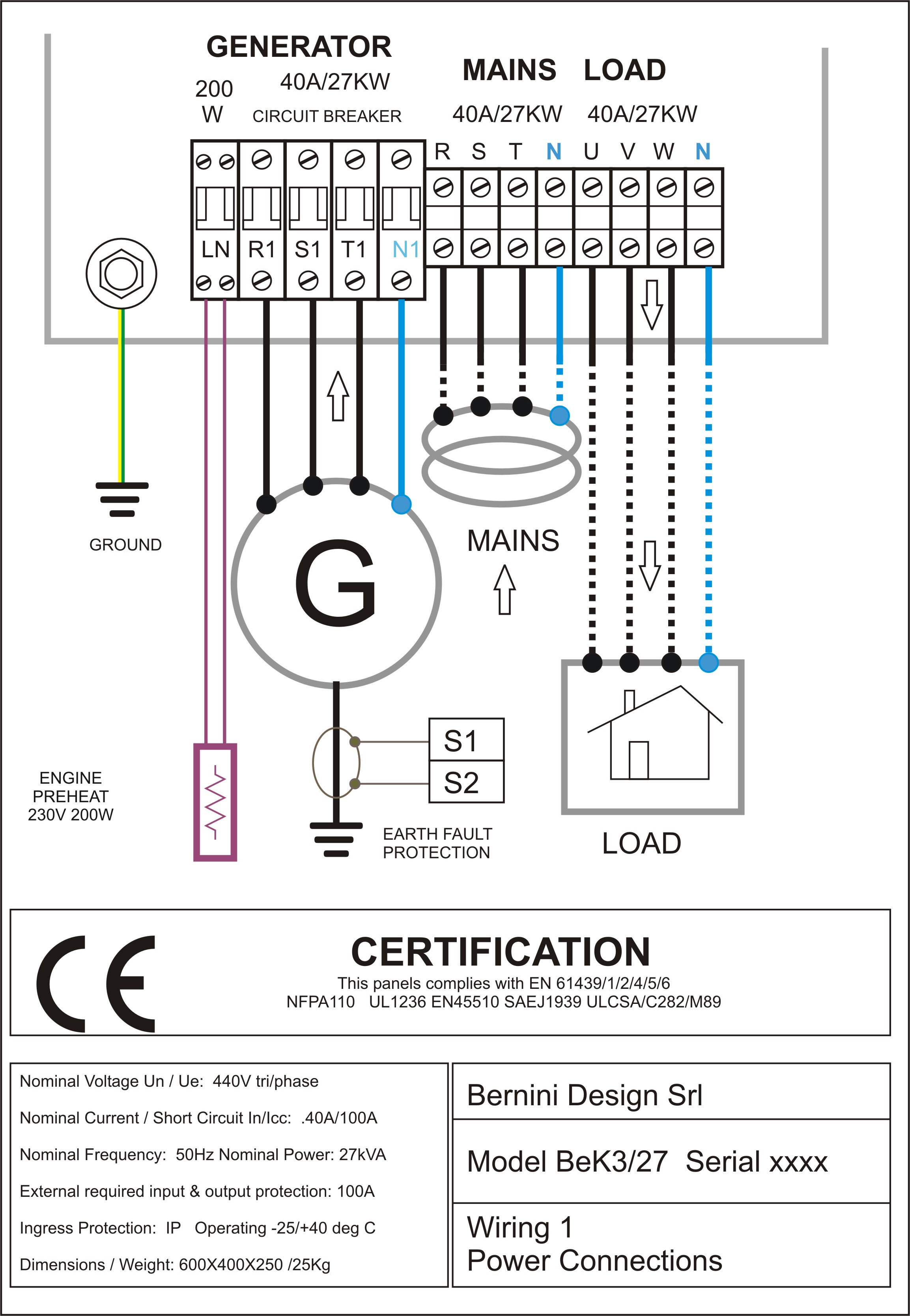
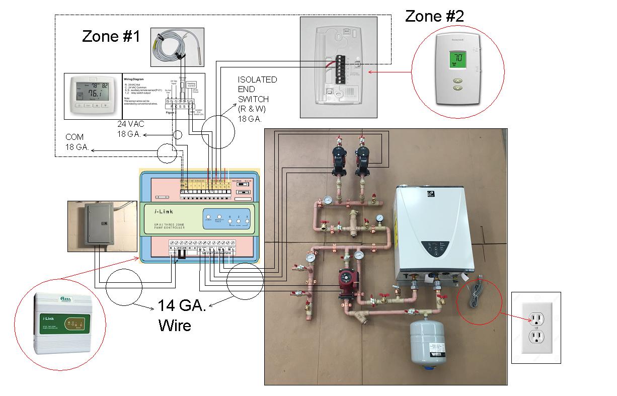
The controller will guarantee remote control monitoring and functionalities when utility power is outside limits. Amf control panel circuit diagram pdf description. An amf panel equipped with bek3 is designed to work with the power generator engine battery. Low voltage wiring photocell occupancy sensor lumacan low voltage relay 10 relay 7 relay 9 relay 8 relay 5 relay 1 relay 2 relay 3 relay 4 to lights zone 2 zone 1 zone 2 zone 1 zone 1 relay 6 greenmax window office area multiple zones. This relay panel controls the operation of heating cooling heat pump and dual fuel systems. Elevator control boards 2348 010 rev a or higher.
Wbsetcl tech spec rev 2 page 5 of 66 control relay panel 600 panel description construction and formation. Relay panel 21 overview the relay panel is a wall mounted low voltage panel that enables the communicating zone950 control to operate with 24 vac hvac equipment. Only three wires are required from the control to the relay panel. 4 table 2 nema and iec terminal markings. A wiring diagram is a streamlined traditional photographic representation of an electrical circuit. For specific wiring.
It shows the elements of the circuit as streamlined shapes and the power and signal links between the gadgets. 68 blocking or out of step relay 69 permissive control device 71 level switch 72 dc circuit breaker 74 alarm relay 75 position changing mechanism 76 dc overcurrent relay 78 phase angle measuring or out of step relay 79 ac reclosing relay 81 frequency relay 83 automatic selective control or transfer relay. All relay switch contacts are shipped as shown in figure 3 but may have transferred during shipping. A the control and relay board panels for 400kv system shall be duplexsimplex type as applicable as per bus configuration so as to accommodate all the control equipment breaker relays meters etc. Wiring diagram book a1 15 b1 b2 16 18 b3 a2 b1 b3 15 supply voltage 16 18 l m h 2 levels b2 l1 f u 1 460 v f u 2. Assortment of electrical control panel wiring diagram pdf.
Use this manual with the following models only.
