Literally a circuit is the course that enables electricity to circulation. In case the connections are reversed the contactor wont close.

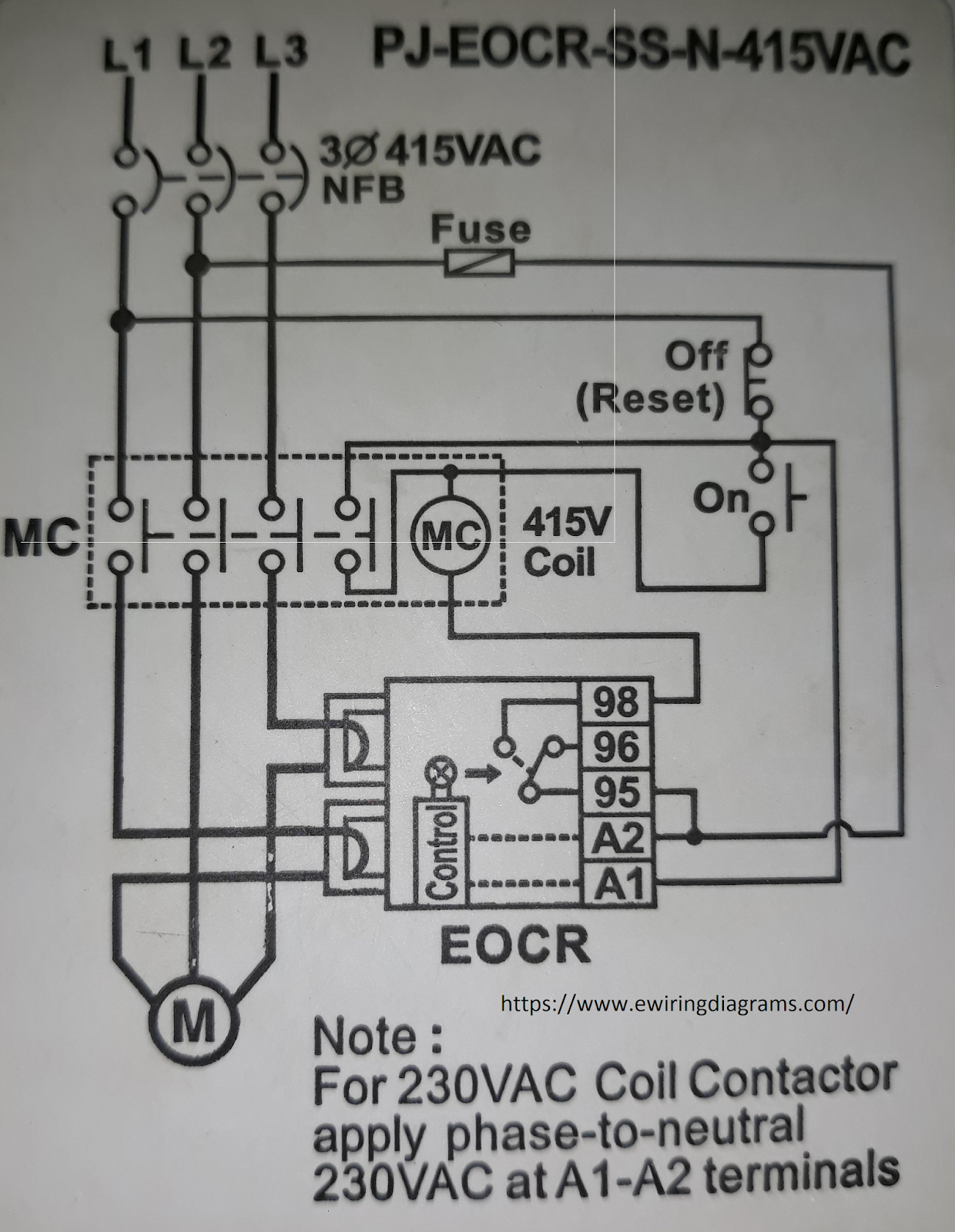
The Beginner S Guide To Wiring A Star Delta Circuit
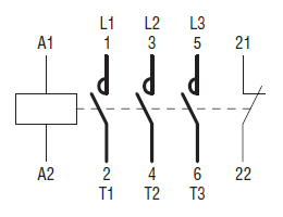
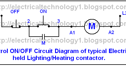
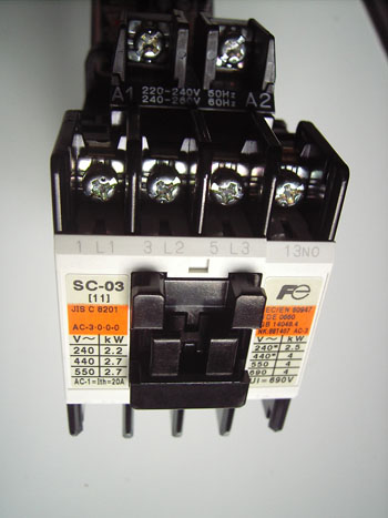
Contactor wiring diagram a1 a2. Contactor relays eaton wiring manual 0611 5 4 5 5 coil connections on the top positioned terminals a1a2 of the contactor diler the following accessories are connected to limit the relay coil switch off breaking voltage peaks. If you recognize. Correcting the wiring will fix the trouble. The function is the same. Variety of contactor wiring diagram a1 a2. Wiring diagram book a1 15 b1 b2 16 18 b3 a2 b1 b3 15 supply voltage 16 18 l m h 2 levels b2 l1 f u 1 460 v f u 2 l2 l3 gnd h1 h3 h2 h4 f u 3 x1a f u 4 f u 5 x2a r.
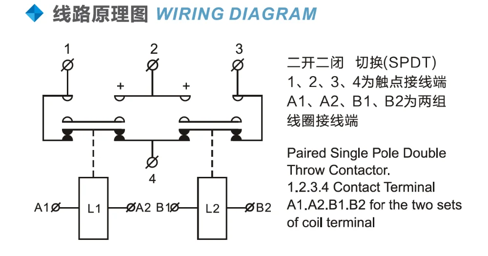
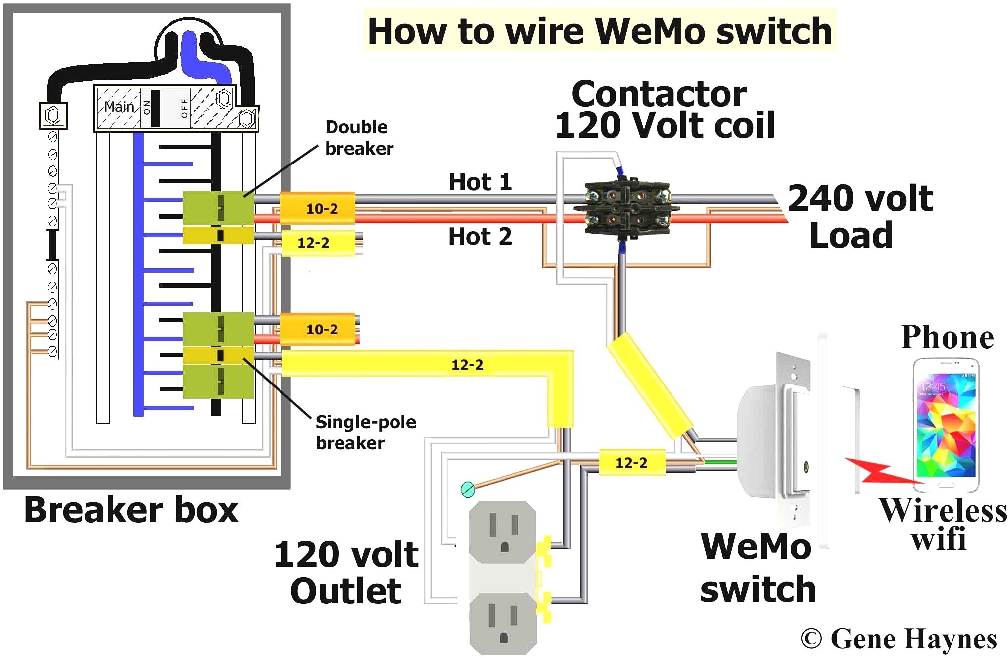
However this misconnection wont destroy the contactor. 2 pole contactor wiring diagram 2 pole contactor wiring diagram download 2 pole contactor wiring diagram for in a1 a2. Contactor wiring diagram a1 a2 a novice s overview of circuit diagrams. A wiring diagram is a simplified standard pictorial depiction of an electric circuit. It reveals the parts of the circuit as simplified shapes and also the power and also signal connections between the devices. Ive not had to do a contactor before and just want to check the wiring of it.
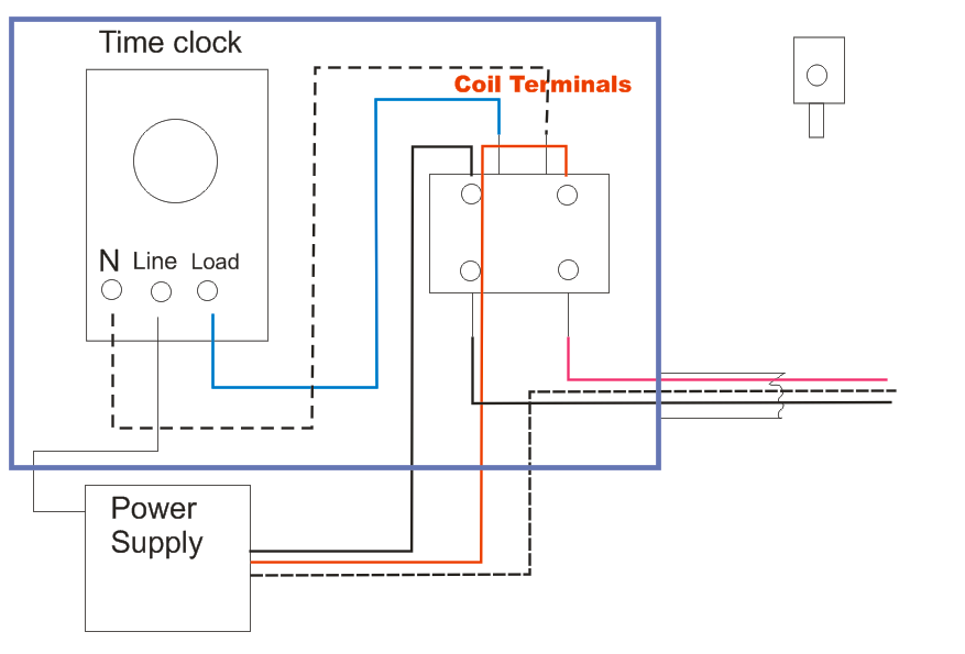
Its a 2 pole contactor with a1a2 and 1234 am i right in thinking that a1 perm live a2 neutral 1 live to light 2 switched live not really sure on 3 and 4 thanks for any advice. I am just double checking as one of my electricians replaced a old consumer unit last week and swears blind there was not a connection in a1 some times lazy buers will loop from a live going to the contactor and switch the neutral such a small loop can be overlooked. Rc suppressors free wheel diode suppressors varistor suppressors on the contactor relay dila the coil. M a1 a2 m. On tesys d with coil dc only lcxdbbe the polarity shall be respected. Contactor breakers limit switch no static control.
A first take a look at a circuit layout could be confusing but if you can read a metro map you can read schematics. The poles a1 and a2 are noted without sign or. The poles are noted a1 and a2. And neutral in a2 so that the contactor clicks in. Obtaining from factor a to aim b.
