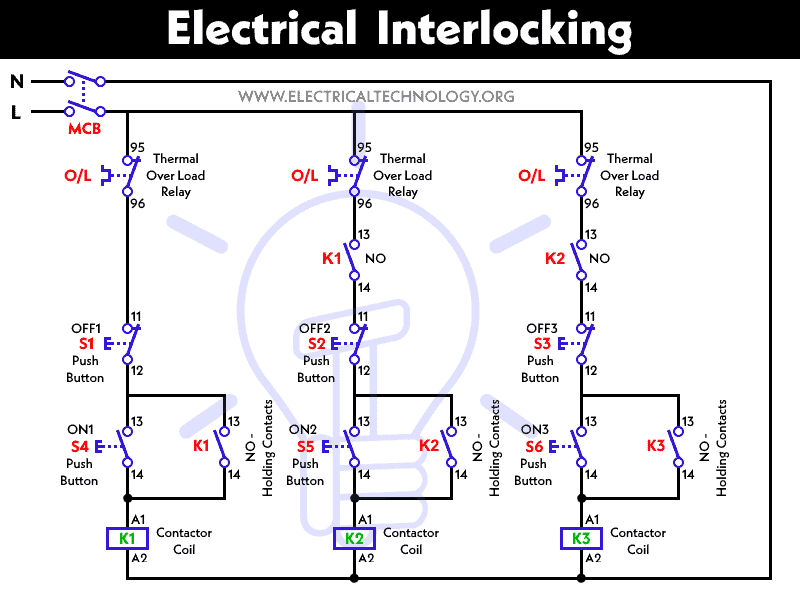
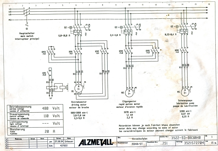
How to wire a contactor. In short we may change the motors operation and control by doing some modification in the above simple electrical interlocking control circuit diagram.

Interlocking Functions Of Plc Program Of Ladder Diagram Plc One
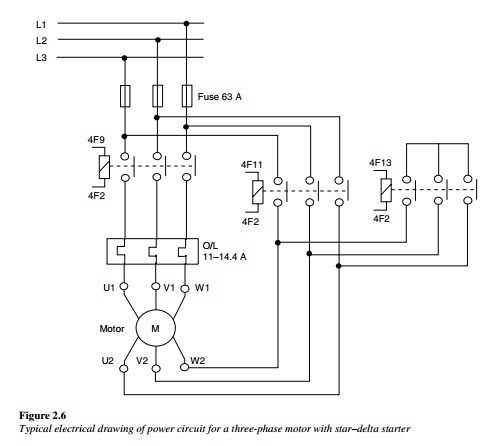
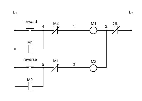
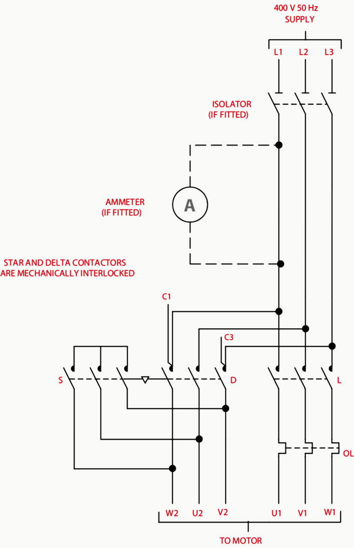
Contactor interlock wiring diagram. Full voltage reversing 3 phase motors. That diagram is using the older standard jic symbology and those dotted lines depict a machanical interlock. A technique called interlocking is used to prevent the contactors from being energized simultaneously or closing together and causing a short circuit. In the bygone days when we used jic standards you were required to have both mechanical and electrical interlocks on reversing 2 speed and wye delta starters this is no. These lines far exceed the 120 volts ac standard in most homes. Wiring diagram since wiring connections and terminal markings are shown this type of diagram is helpful when wiring the.
It uses two contactors two auxiliary contact blocks an overload relay a mechanical interlock two normally open start pushbuttons a normally closed stop pushbutton and a power supply with a fuse. An interlock is a feature that makes the. For example if we need that motor 1 should stop when motor 3 starts to run then we may use a normally close nc link of m3 in line 1. The electrical interlock is inherent in the wiring scheme. 240 volts ac and 480 volts ac are commonly used for these large pieces of. This diagram is for 3 phase reversing motor control with 24 vdc control voltage.
Many large pieces of equipment are powered directly from high voltage lines. Interlock connection fixed adjustable fixed res heating element h adjustable by fixed taps res. Contactor breakers limit switch no static control standard elementary diagram symbols.

