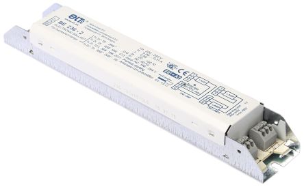
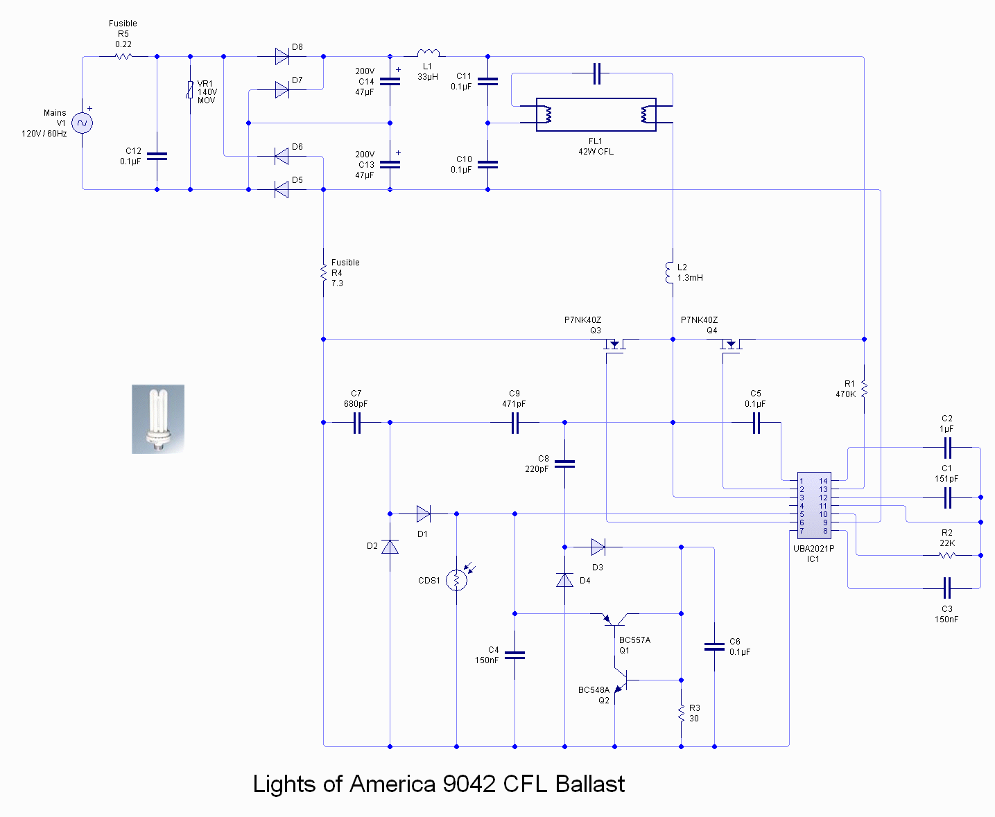
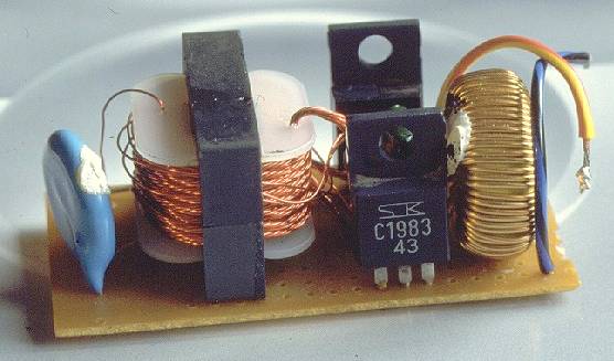
Electronic ballast ya electronic choke ko tube light frame mein kaise install kiya jata hai aur uski wiring connection kaise kiye jate hai. Approximately four tube circuits could be operated from a single set of two mosfets measured to match the power level.

Electrical Wiring Systems And Methods Of Electrical Wiring
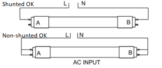
Circuit diagram of double tube light set using double choke. Rajput technical 1214785 views. A fluorescent light does not have the usual glowing filament of an incandescent bulb but instead contains a mercury vapor that gives off ultraviolet light when ionized. For this application of fixtures for tube lights one socket will have the live power and the other socket will serve solely as a lamp holder. How to install a single tube light with electromagnetic ballast. This is shown in the following image which features the led tube light connection diagram. This article gives a details about double tube light connection by using single ballast or choke some electronic choke not support this connection check the ballast specification and watts level before make this type of connection.
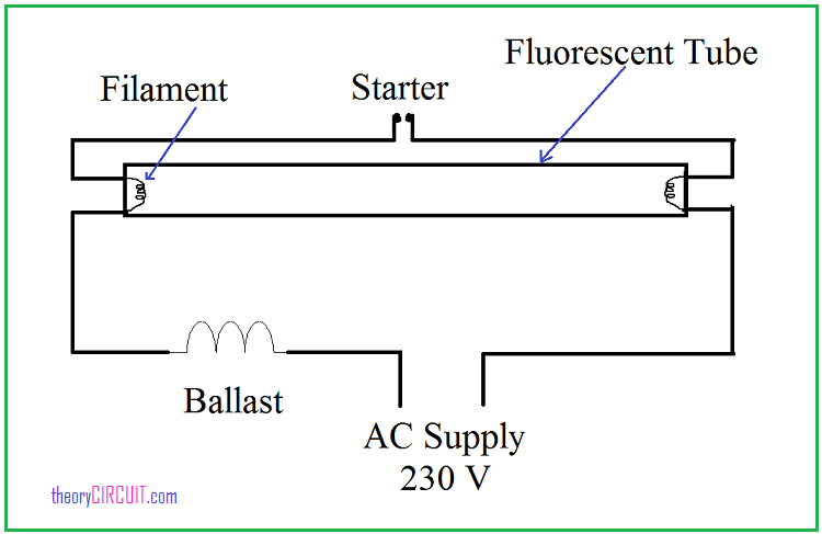
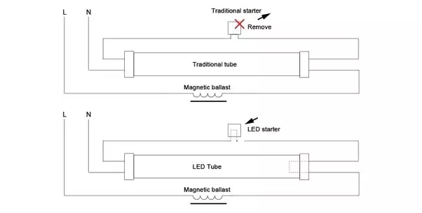
Wiring diagram here two tube lights are used in our case each one is 20 watts each tube light will have. Fluorescent starters are used in several types of fluorescent lights. Here is one example of a tube light fixture consisting of a large heavy square choke or ballast and a small cylindrical starter lets try to understand how the whole system works. When we connect the ac supply voltage to the circuit then the starter act like short circuited and current flow through those filament located at the first and second end of the tube light and the filament generate heat and it ionized the gas mercury vapor in the fluorescent tube lamp. A double switch allows you to operate two lights or appliances from the same location. No power will be run to the other end the diagram below is for single end led t8 ballast bypass lamps.
For example you might want to turn on a bathroom light separately from the ceiling fan. From the junction box the neutral wire is not taken out to the switch board rather it is taken out from the junction box and carried out to the port 2 of the tube light as per figure above. How to check tube light choke starter capacitor cfl bulb soldering iron by using series test duration. The ultraviolet light makes particles that coat the inside of the tube and these particles glow or fluoresce see how fluorescent lamps work for details. Double switches sometimes called double pole allow you to separately control the power being sent to multiple places from the same switch. So the neutral wire is continued from port 2 to pin 1 of terminal 2.
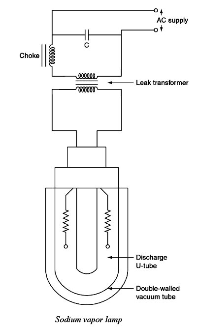
The starter is like a key of fluorescent light because it is used to light up the tube. Electrical evam electronic choke ki working mein kya. Please refer to the circuit diagram on the right as you read the following points. The choke is in fact a large inductor. A wire already connects port 2 and pin 1 of the terminal 2. The 40 watt fluorescent lamps are controlled in parallel each using its own l c resonant circuit.
Observe that we have a built in dead time of 12 ps in the ir2151 driver to stop shoot through currents in the half bridge.
