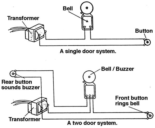
Wiring for two doors is the same as for one with the transformer hardwired to the 120 volt source from a house circuit. Circuit diagram and explanation.

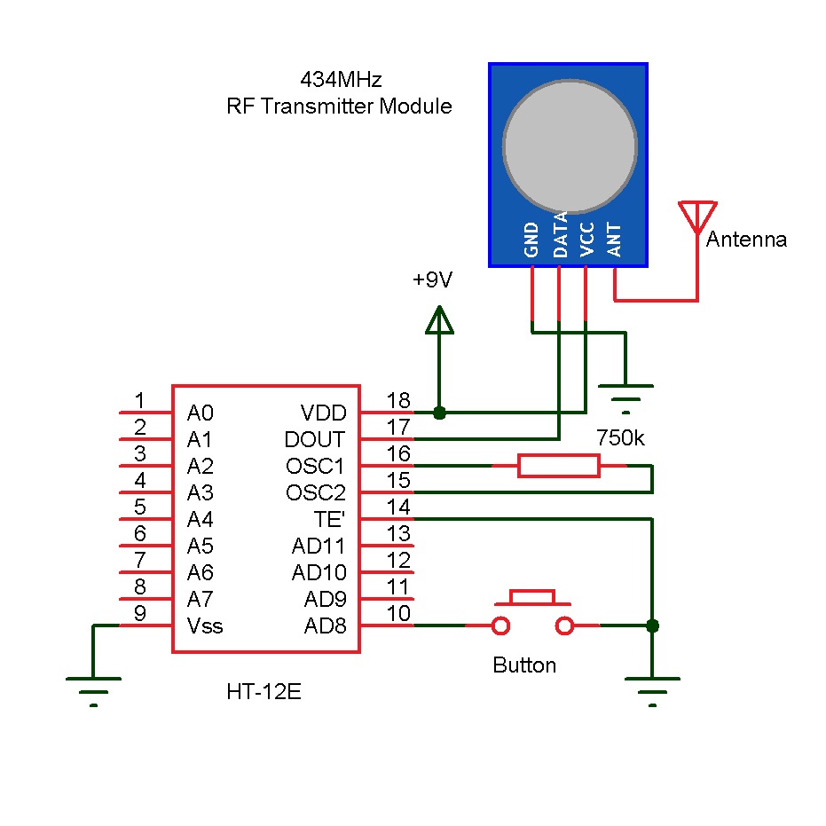
Wireless Doorbell Transmitter 3 Steps With Pictures
Circuit diagram of doorbell. The ic has an in built circuitry to produce ding dong sound each time its pin 3 is pulled low. Variable resistor rv1 is used to control the ring duration means how long will be the output pin 3 will be high. Listening same door bell tune at always may be boring this melody generator doorbell circuit may help us to avoid this dull situation because this circuit provides 12 tonesthis multi tone door bell circuit produces 12 types of musical toneyou get twelve popular tones in sequences that gives a new dimension to musical door bells. So it keeps on ringing as the switch or button is pressed. Wiring diagram for a two chime doorbell. Above figure shows the circuit diagram for doorbell.
Almost everyone uses it. The circuit of the wireless bell shown here is easy to built and using only few easy to find low cost components. This simple and cost effective ding dong electronic doorbell circuit is based on ic 8021 2. Connect the input wires on the transformer to the source circuit using the black to black white to white and ground to green method. The main feature of this doorbell circuit is that we can control its time duration. Here we can see that first 555 timer ic is configured in monostable mode means it will go high and low only once if triggered with trigger pin 2.
A um66 melody generator is connected at the output of the receiver circuit which will be activated when the receiver circuit receives signals from the transmitter. In this tutorial we are going to design a simple doorbell circuit using a 555 timer icit is a very common and useful device. The sound is stored in the ic as bits as in a rom.


