It requires a small amount of control circuit to turn on and off the load. The black power wires will need to be tied together externally such as through a wire nut.

Crankcase Heaters And Single Pole Contactors Hvac School
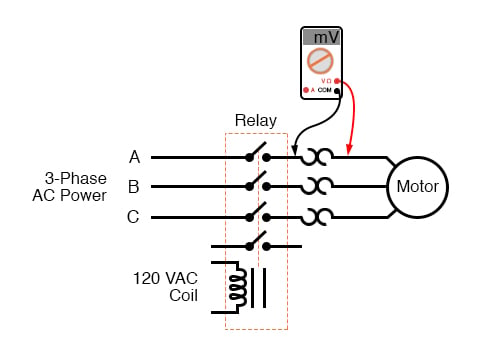
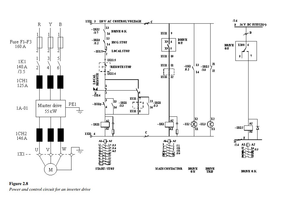
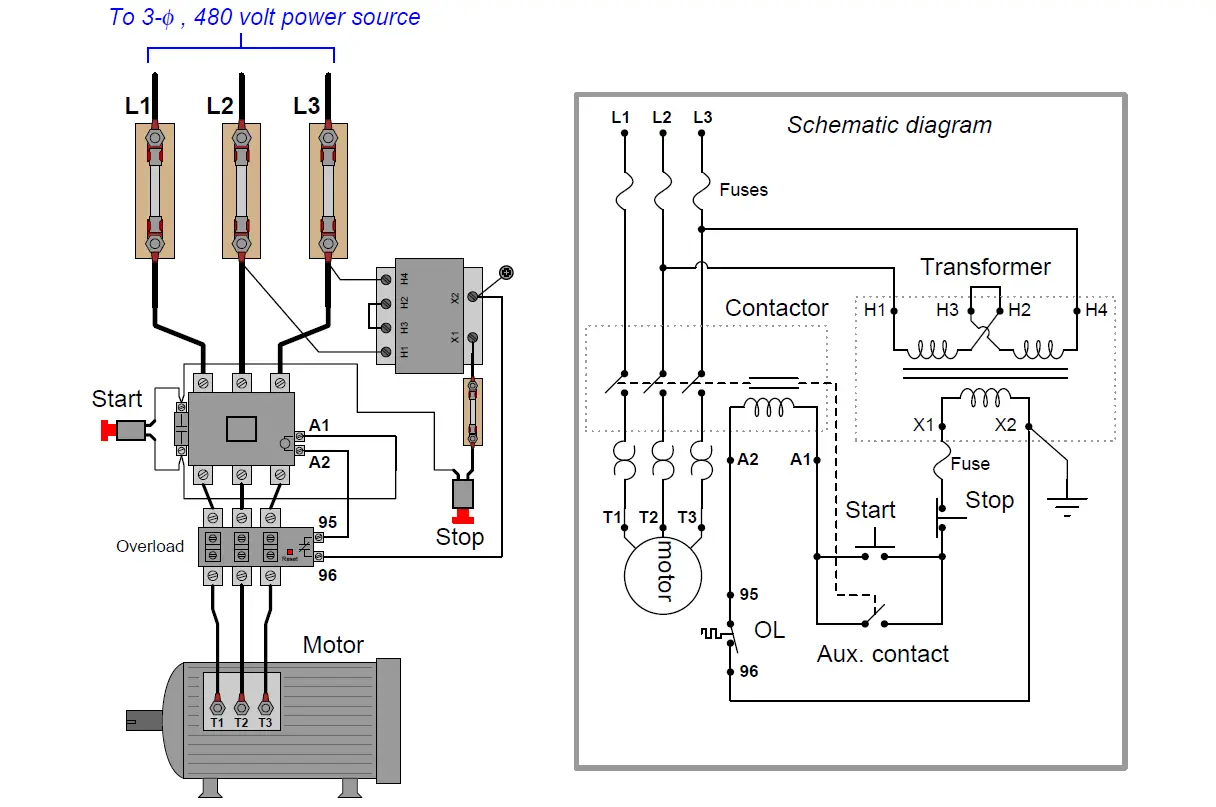
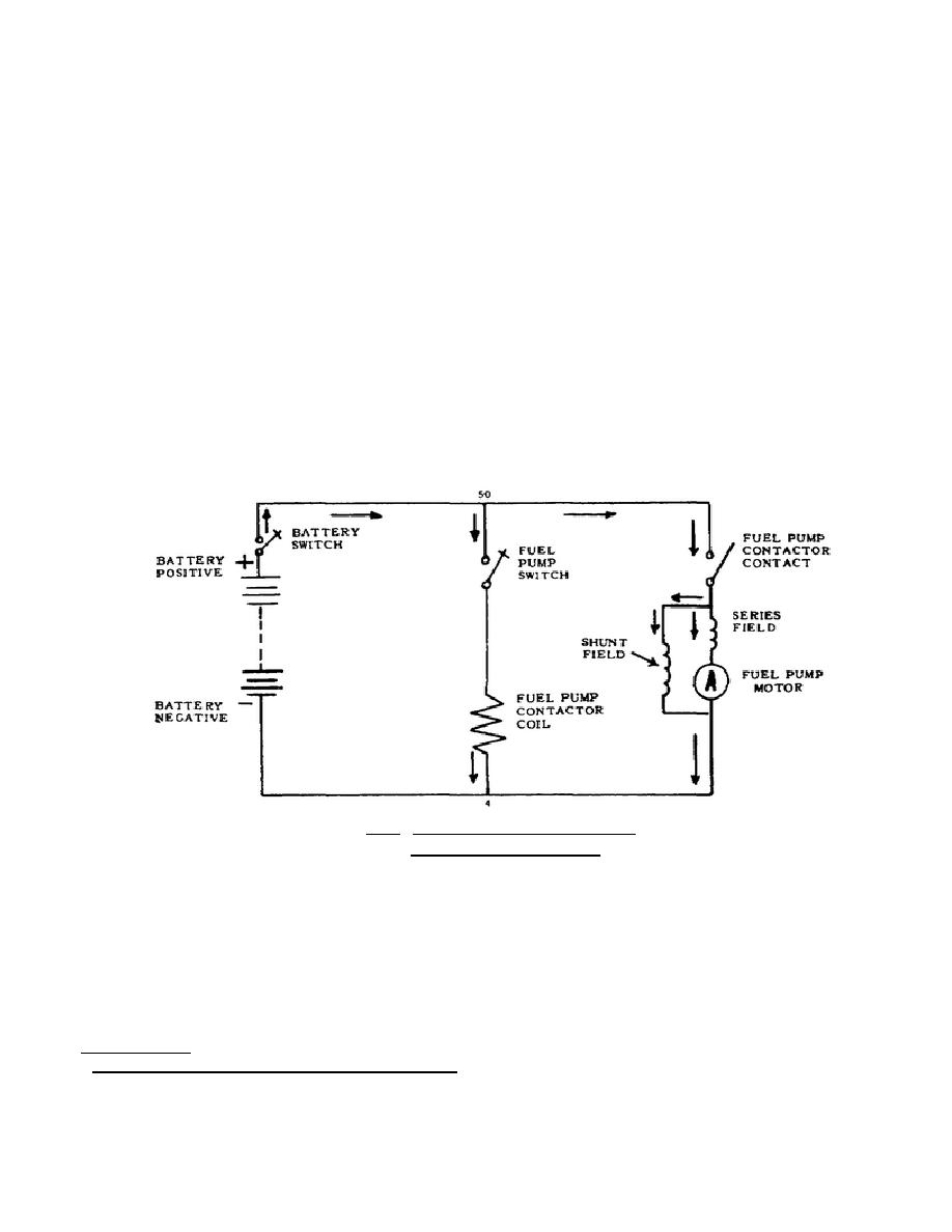
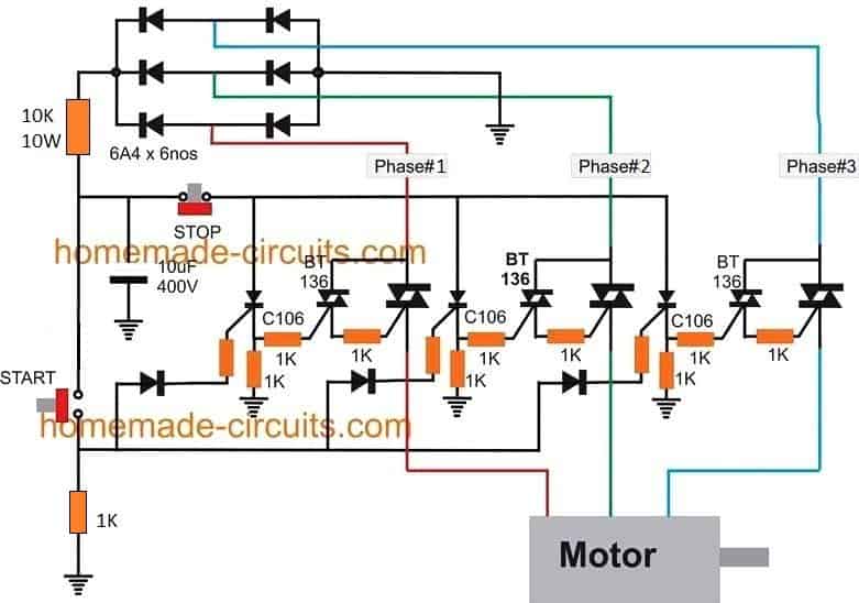
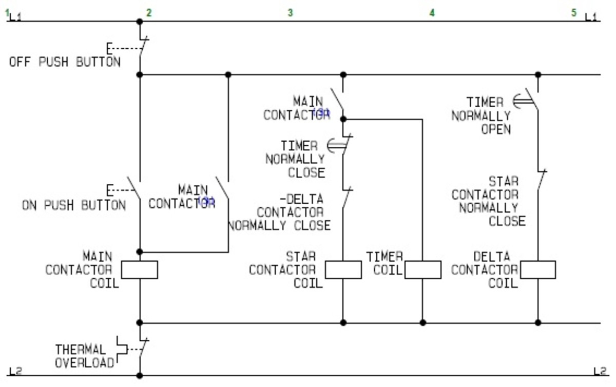
Circuit diagram of contactor. The coil voltage of a contactor or relay can be installed for virtually any control circuit voltage to provide complete flexibility for these devices both ac and dc as the. Contactor wiring diagram pdf download. Posted on may 9 2018 august 9 2018 by headcontrolsystem. Magnetic contactor circuit diagram luxury thermal overload relay. In the above one phase motor wiring i first connect a 2 pole circuit breaker and after that i connect the supply to motor starter and then i do cont actor coil wiring with normally close push button switch and normally open push button switch and in last i do connection between capacitor. Collection of ac contactor wiring diagram.
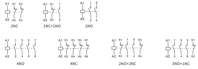
One contactor may have several auxiliary contacts either normally open or normally closed if required. Referring to the given diagram we can see a simple circuit comprising of a tp relay. A wiring diagram is a streamlined conventional photographic representation of an. Note that one one of the contactor acts as a switch for the start button. The auxiliary contact is often used in a relay logic circuit or for some other part of the motor control scheme typically switching 120 volt ac power instead of the motor voltage. The design of this type of contactor is most advanced among all other types of contactors.
Effectively looking the start button closed. Either of the two start buttons will close the contactor either of the stop buttons will open the contactor. Therefore the operation of this contactor is safe compared to manual contactor. The circuit that applies the voltage to the coil is referred to as the control circuit because it controls the main device that the contactor or relay is switching. It reveals the elements of the circuit as streamlined forms and the power and also signal links between the gadgets. A simple circuit diagram.
The contactor will have space for the red power wires coming in from the photocell circuit breaker and lights. This is an electromagnetic type contactor and it can operate automatically. The above diagram is a complete method of single phase motor wiring with circuit breaker and contactor. A wiring diagram is a simplified traditional pictorial representation of an electrical circuit. The explained circuit will effectively switch the connected appliances to the generator mains during power failure however it wont be able to switch start the generator automatically this will need to be done manually because most generators involve a difficult mechanical actuation procedure. The lights connect to the output ports on the contactor.
Collection of contactor wiring diagram pdf.
