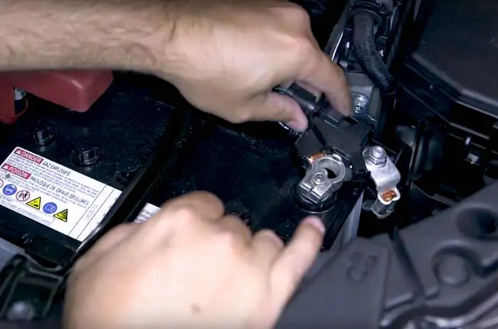
The 47225 brake control utilizes time based actuation for applying braking power to the trailer brakes. Make sure that both positive and ground connections are made directly to the tow vehicles battery.

What Is A Brake Controller And How Do They Work Elecbrakes
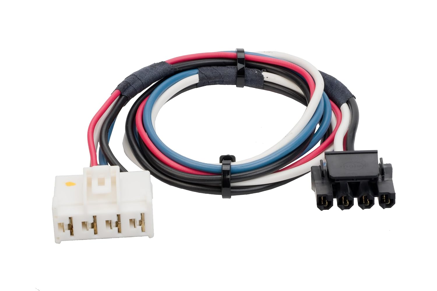
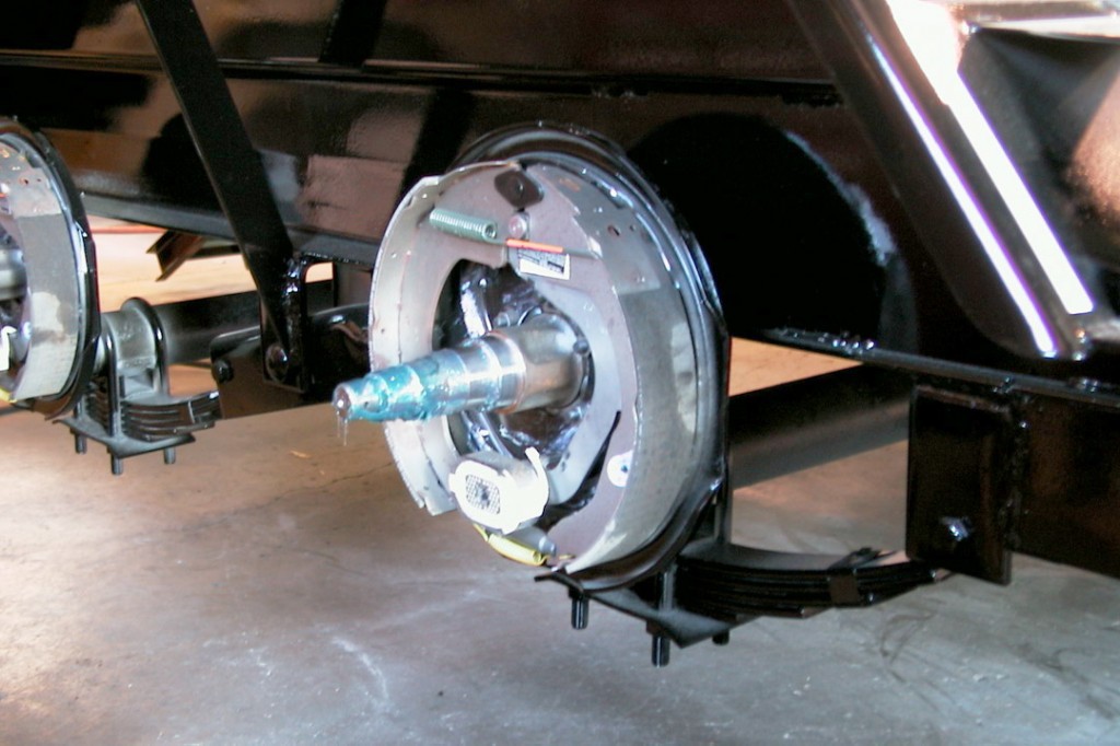
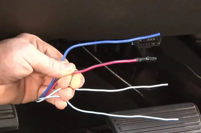
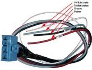
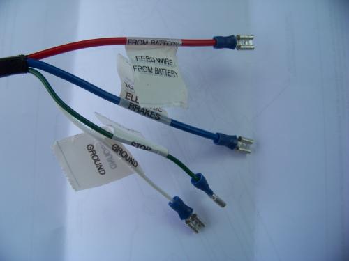
Brake force brake controller wiring diagram. If your vehicle came equipped with a factory tow package brake control function wires may exist under the vehicle. Each model of electric trailer brake controller we offer has unique features that are sure to meet your specific trailer brake control needs. This brake control is designed to operate with electric trailer brakes and not electric hydraulic brake systems. The four wires on the brake controller will be connected shortly. Connecting to existing wiring or chassis ground other than the battery terminal may damage vehicle circuits and could lead to trailer brake failure. Important facts to remember 1.
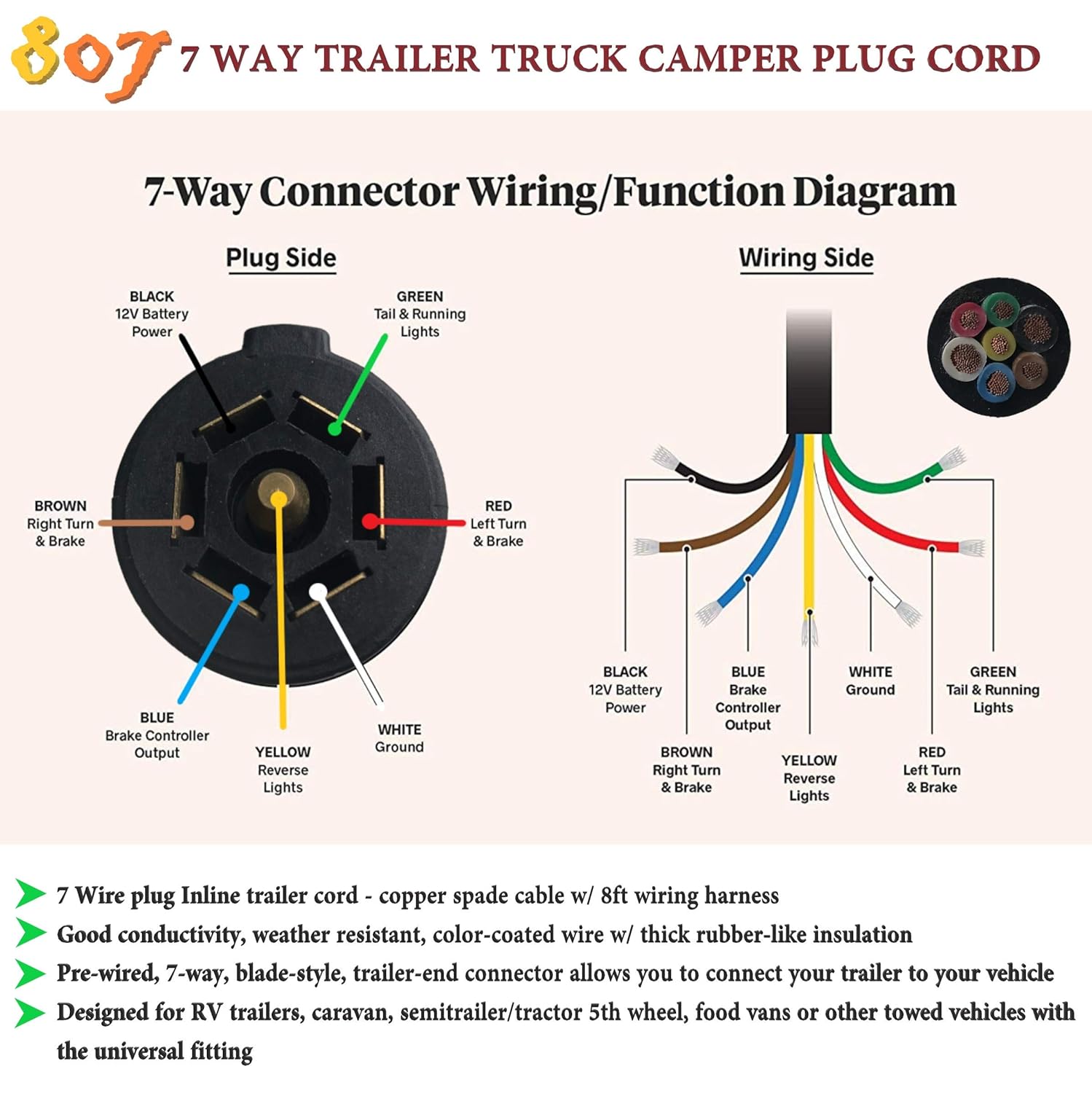
The brake control must be installed with a 12 volt negative ground system. Generic wiring diagram read this first. The brighter the glow the more braking force is being applied to the trailer brakes. From the time based output models to the inertia mechanical motion sensor units these electric trailer brake controllers are among the best systems available. Wiring the 7 way trailer connector and brake controller. Most states and provinces require a trailer brake controller based on the weight of the trailer.
Read and follow all instructions carefully before wiring brake control. Secure the brake controller into the mounting bracket. An led indicator will glow displaying braking intensity. Return to the duplex cable under the hood where the brake wire now white needs to be separated from the 12 volt hot lead black. The brake forcetm came equipped with a quick connector plug wired to the back of the controller. Keep these instructions with the brake control for future reference.
