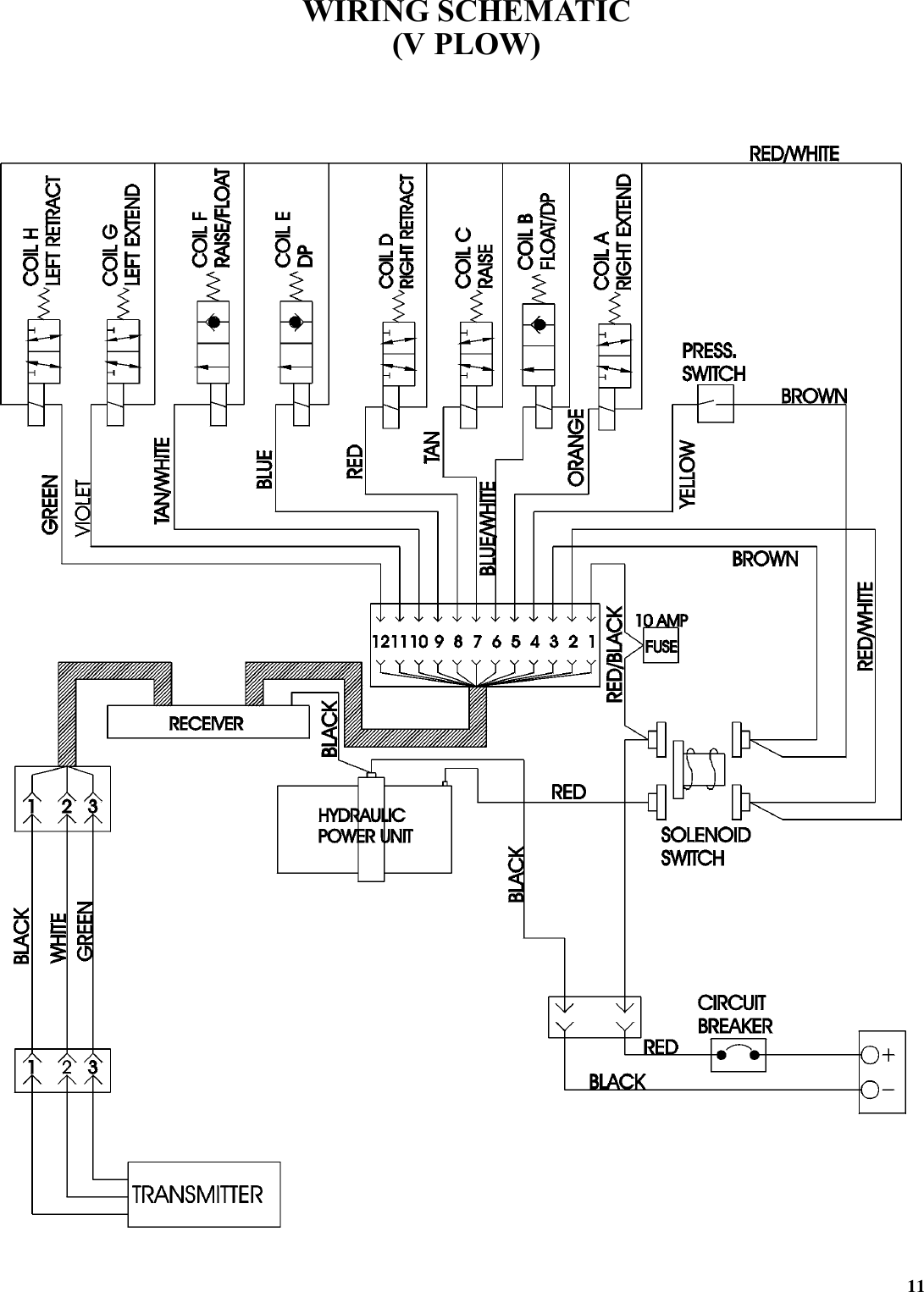
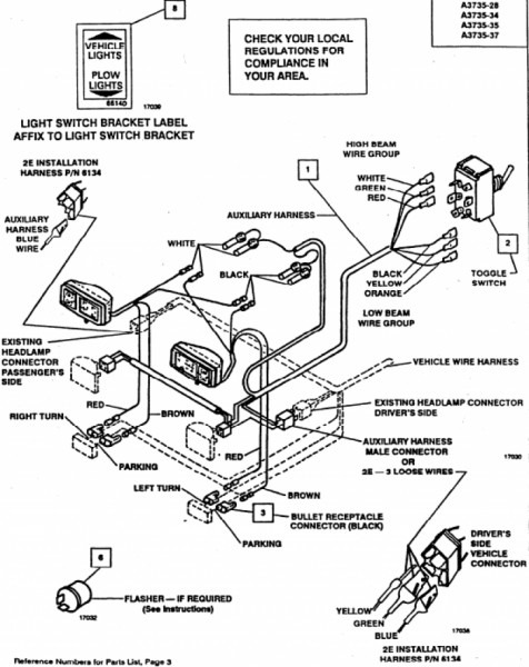
Variety of boss plow controller wiring diagram. 8272004 95947 pm.

888239 Boss Rt3 V Blade Wiring Diagram Wiring Resources
Boss v plow controller wiring diagram. It shows the elements of the circuit as streamlined forms as well as the power and signal links between the devices. When plowing on a solid level area parking lots roads and driveways plow shoes can be raised up to increase cutting edge contact on the plowed surface. Giving snow and ice removal professionals everything they need to restore order when winter weather brings chaos. I followed the boss flow chart. My controller does not light up. They know your plow well and want your complete satisfaction.
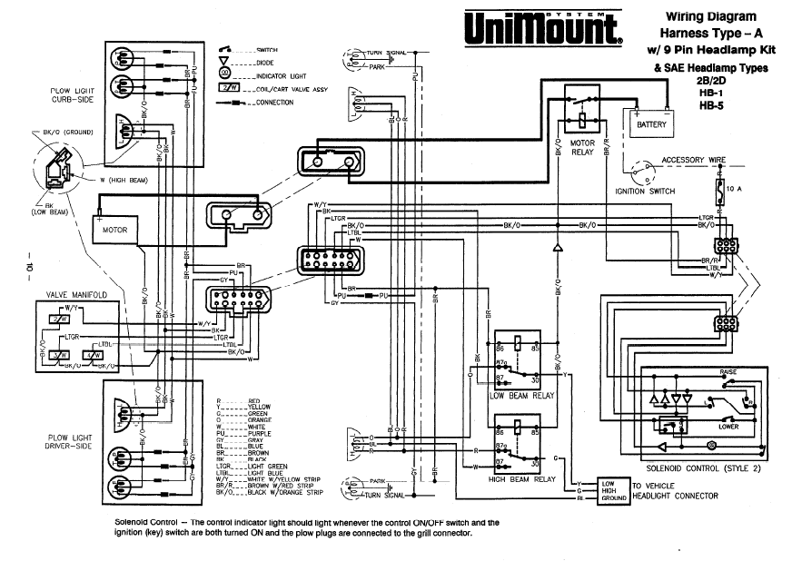
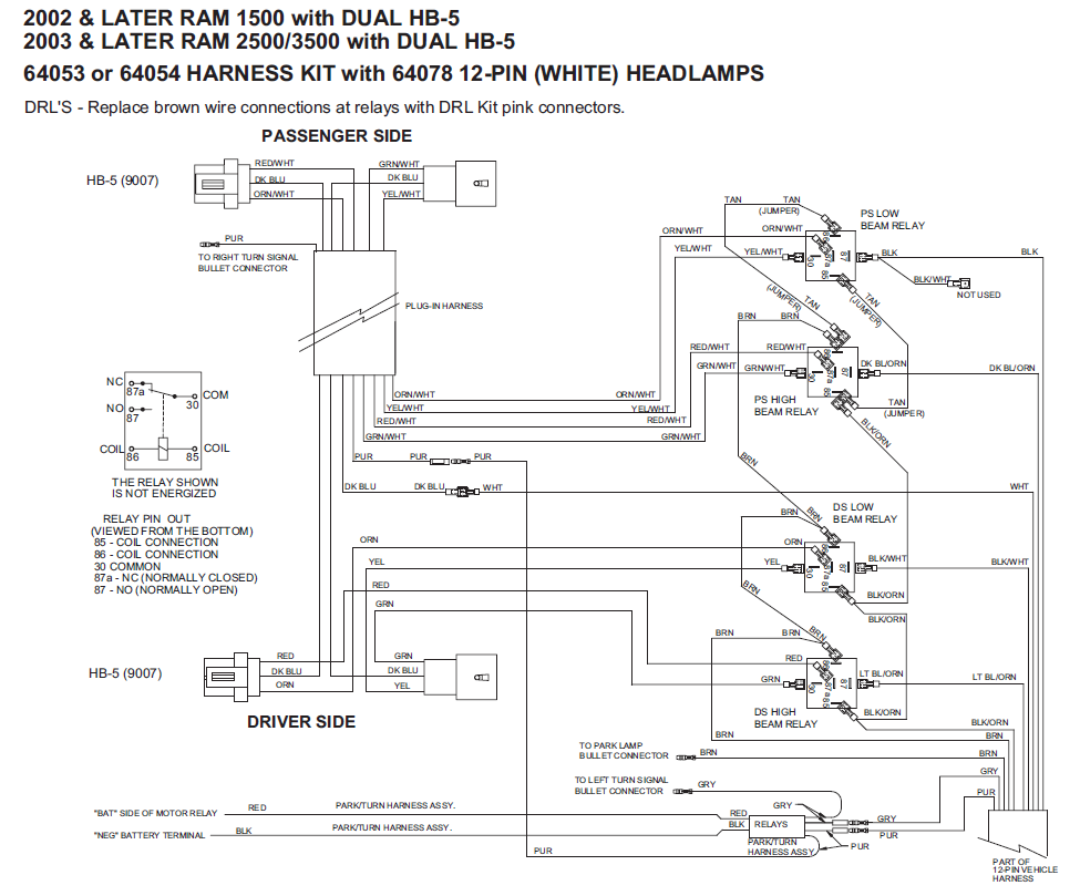
When plowing dirt gravel or grass plow shoes should be lowered below the cutting edge surface to prevent the plow from digging into the plowed surface. Electrical system wiring schematic truck side electrical system wiring schematic truck side g10272. It reveals the parts of the circuit as simplified forms and the power as well as signal links in between the gadgets. A wiring diagram is a streamlined conventional photographic representation of an electric circuit. If you have further questions your local boss plow dealer is the person to talk to. Boss snow plow wiring diagram boss rt3 v plow wiring diagram boss snow plow installation manual boss snow plow wiring diagram every electrical structure is made up of various distinct pieces.
If not the arrangement wont work as it ought to be. Genuine boss parts everything we do at boss comes back to one goal. Collection of boss v plow wiring diagram. Electrical system wiring schematic plow side g10271. The boss snow plow wiring diagram simple wiring diagram for boss snow plow boss plow wiring diagram v boss v plow wire harness installation boss snow plow wiring harness. Thanksgiving we installed all the plows on the trucks.
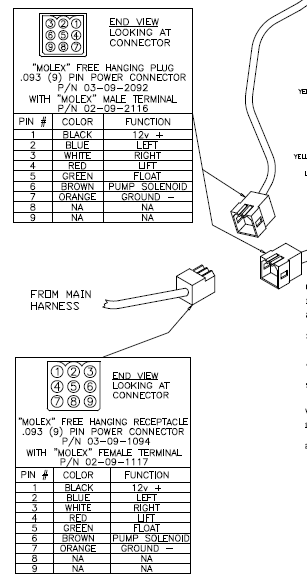
Microsoft word 13 pin wiring schematicdoc author. 4 snowplow operation. Yesterday we installed the 86 sb smarthitch2 on the truck and no movement. Wiring diagram smartlight2 wiring schematic smartlight2 control plug pin functions. The plow is mounted on the vehicle. A wiring diagram is a simplified standard photographic depiction of an electrical circuit.
11 rt3 power v blade with smarthitch wiring schematic figure 6. I have power at the fuse box. Rt3 power v blade with smarthitch wiring diagram figure 5. I do have power on the black wire in the controller plug. Each component should be set and connected with different parts in particular way. Thats why we never stop pushing our designs engineering and innovations to help make your job easier and more productive.


