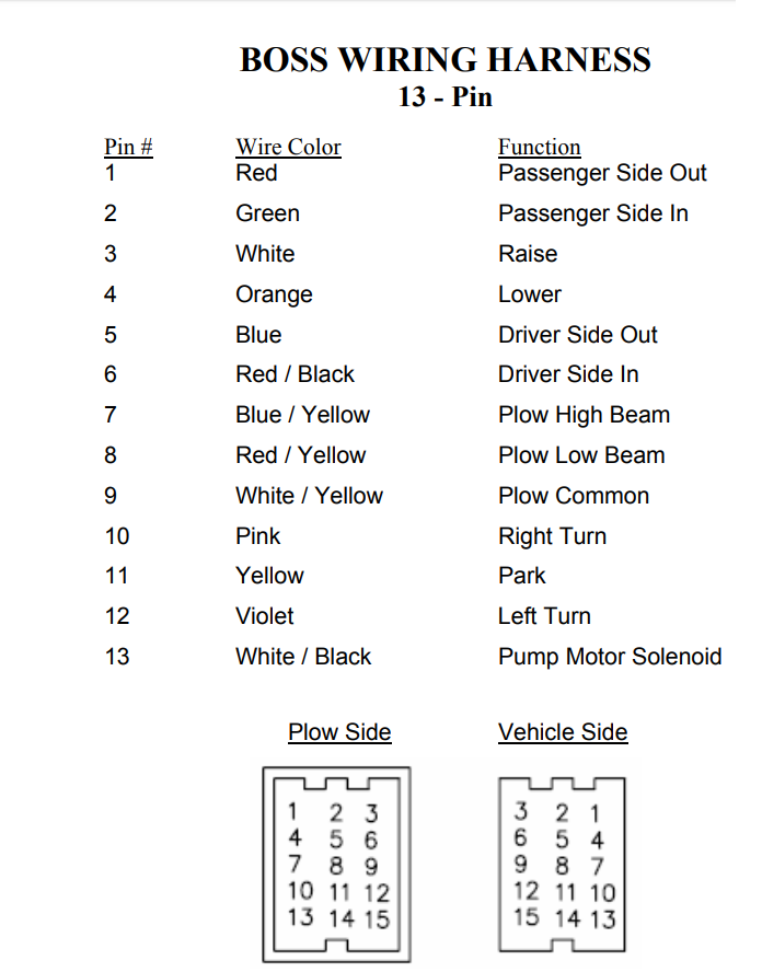
Snowplow assembly procedure 4 snowplow assembly procedure note. 6 red black driver side in.

Fisher Plow 11 Pin Wire Harness Diagram Cylinder
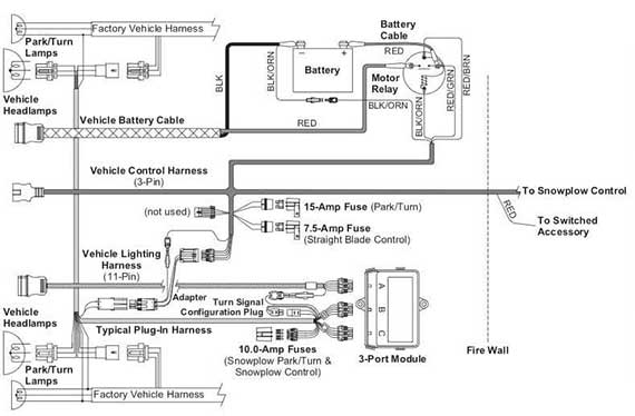
Boss snow plow wiring harness diagram. It shows the elements of the circuit as streamlined forms as well as the power and signal links between the devices. A wiring diagram is a simplified standard photographic depiction of an electrical circuit. Shoe assembly g10059 1. Recommended vehicle models refer to the boss snowplow application chart and selection guide. 8272004 95947 pm. Electrical system wiring schematic plow side g10271.
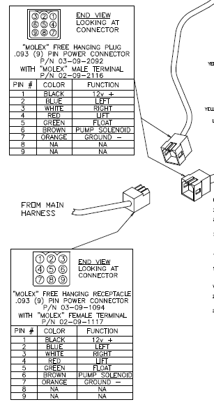
Electrical system wiring schematic truck side electrical system wiring schematic truck side g10272. Secure wiring harness g10126 33. Secure wiring harness 61 to light bar 13 using wire ties as shown above. 2 green passenger side in. 50 out of 5 stars 4. Control harness and powerground cable connectors for corrosion.
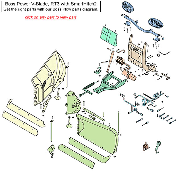
Begin the assembly procedure by cutting down each corner of the plow box so that each wall of. 7 gray black plow high beam. Wiring diagram smartlight2 wiring schematic smartlight2 control plug pin functions. Rt3 v blade manifold wiring diagram 20. Part numbers and illustrations may vary. Boss wiring harness.
Snow plow wiring harness repair kit msc04753 msc04754 for boss snowplow blade. Collection of boss v plow wiring diagram. The boss snowplow has been carefully designed and built for years of carefree. 10 pink right turn. 5 blue driver side out. 9 n a n a.
11 pin. 11 rt3 power v blade with smarthitch wiring schematic figure 6. Boss hand held kit with electrics v plow msc015100. This manual is used for the assembly of all standard super and heavy duty boss straight blade plows. 40 out of 5 stars 1. Microsoft word 13 pin wiring schematicdoc author.
8 gray plow low beam. Msc04317 boss snow plow plow side 13 pin light control harness. The boss snow plow wiring diagram simple wiring diagram for boss snow plow boss plow wiring diagram v boss v plow wire harness installation boss snow plow wiring harness. Pin wire color function 1 red passenger side out. 3 white raise. Rt3 wiring diagram rt3 wiring diagram.
44 out of 5 stars 23. Get it as soon as fri may 29. 4 orange lower.


