Three point manual dc motor starter circuit diagram. Learn how a capacitor start induction run motor is capable of producing twice as much torque of a split phase motor.

Ac Motor Control Circuits Worksheet Ac Electric Circuits
Ac motor starter diagram. Figure 1 typical wiring diagram. A motor starter is a combination of devices used to start run and stop an ac induction motor based on commands from an operator or a controller. Draw a diagram showing how this could be done for a single phase electric motor using two starter contacts. An ac motor converts electric energy into mechanical energy. In the case of common ac that is used throughout most of the united states the current flow changes direction 120 times every second. Click here to view a capacitor start motor circuit diagram for starting a single phase motor.
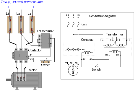
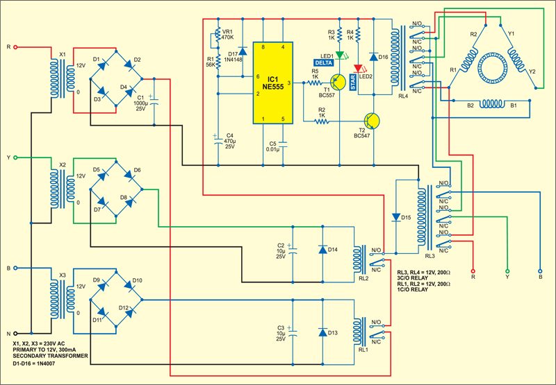
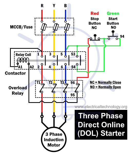
Figure 1 is a typical wiring diagram for a three phase magnetic motor starter. The electromagnet that holds the starter in the run position is in the field circuit. This type of starter can be used for shunt and compound motors and if the field is lost the starter drops out protecting the motor against runaway. Diagram er9 m 3 1 5 9 3 7 11 low speed high speed u1 v1 w1 w2 u2 v2 tk tk thermal overloads two speed stardelta motor switch m 3 0 10v 20v 415v ac 4 20ma outp uts diagram ic2 m 1 240v ac 0 10v outp ut diagram ic3 m 1 0 10v 4 20ma 240v ac outp uts these diagrams are current at the time of publication check the wiring diagram supplied with. They can be used as a guide when wiring the controller. This starter is a so called three point starter.
Also read about the speed torque characteristics of these motors along with its different types. An ac motor uses alternating current in other words the direction of current flow changes periodically. The following line diagram illustrates how a normally open and a normally closed pushbutton might be connected to control a three phase ac motor. With this sort of an illustrative guidebook you will have the ability to troubleshoot avoid and complete your assignments with ease. R for run and s for start. Line voltage control three phase 3ph motor starter controlling a three phase motor rev 08 aug 2006 the above wiring diagram assumes your magnetic starter has a 240v coil.
Ac fan motor wiring diagram youll need a comprehensive expert and easy to know wiring diagram. Wondering how a capacitor can be used to start a single phase motor. If you have a 120v coil instead of running a line from coil overload l2 you must run coil overload neutral. After the motor has had time to speed up another set of starter contacts bypass line power around the resistors directly to the motor windings. They show the relative location of the components. In this example a motor starter coil m is wired in series with a normally open momentary start pushbutton a normally closed momentary stop pushbutton and normally closed overload relay ol.
In north america an induction motor will typically operate at 230v or 460v 3 phase 60 hz and has a control voltage of 115 vac or 24 vdc.


