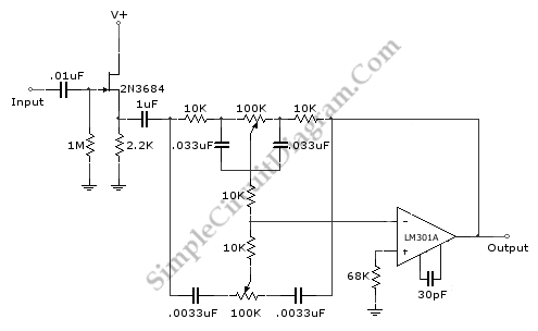
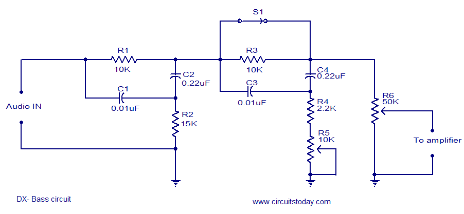
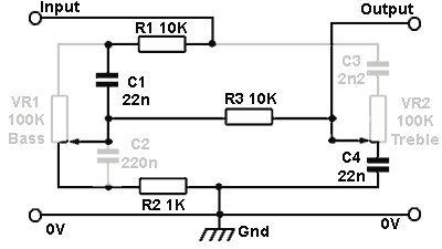
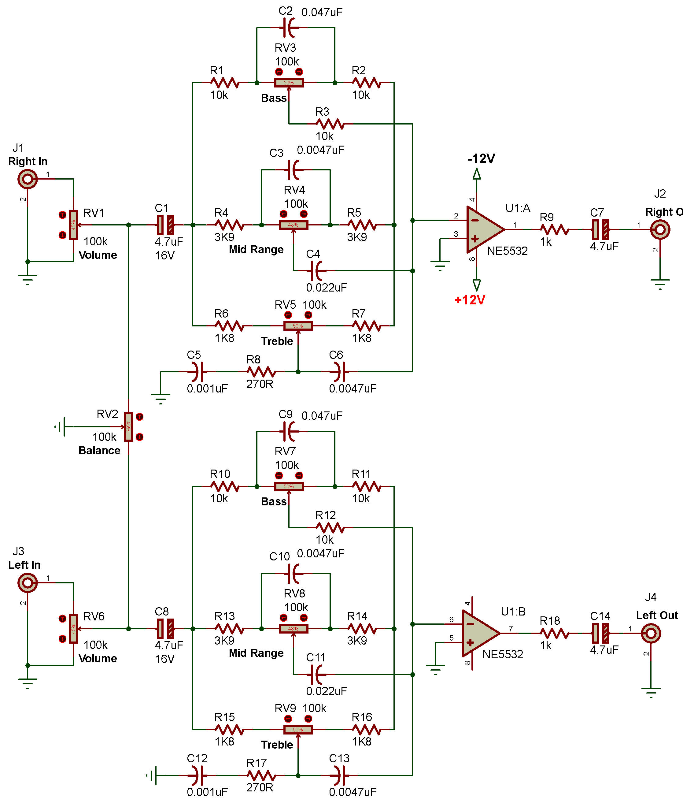
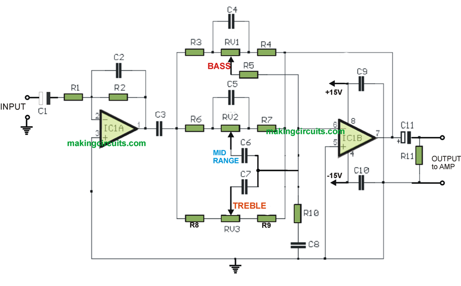
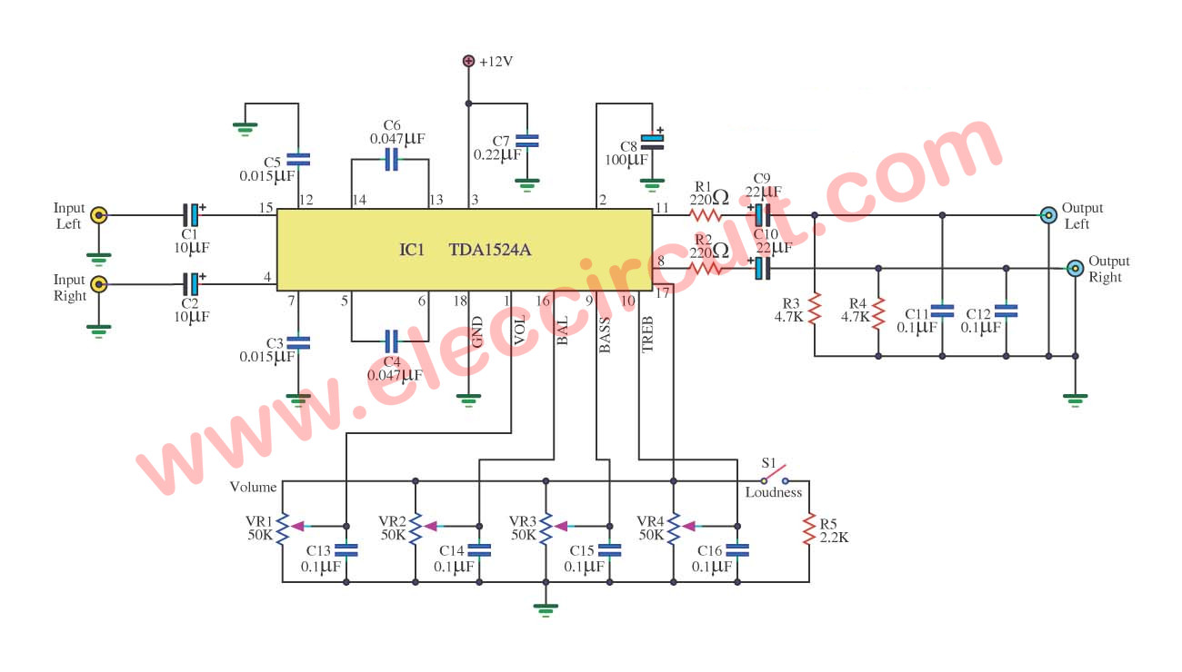
This circuit provides low pass filter of input audio which produces a low frequency of input and high frequency is blocked. The whole bass treble circuit is designed such that it is fit with any stereo systemusing the power supply from the stereo system itself as the total power supply required for this circuit is only 12 volt dc the bass treble circuit is reduced and made more effective.
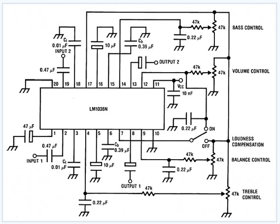
Bass Treble Tone Control Circuit Electronic Circuit Diagram
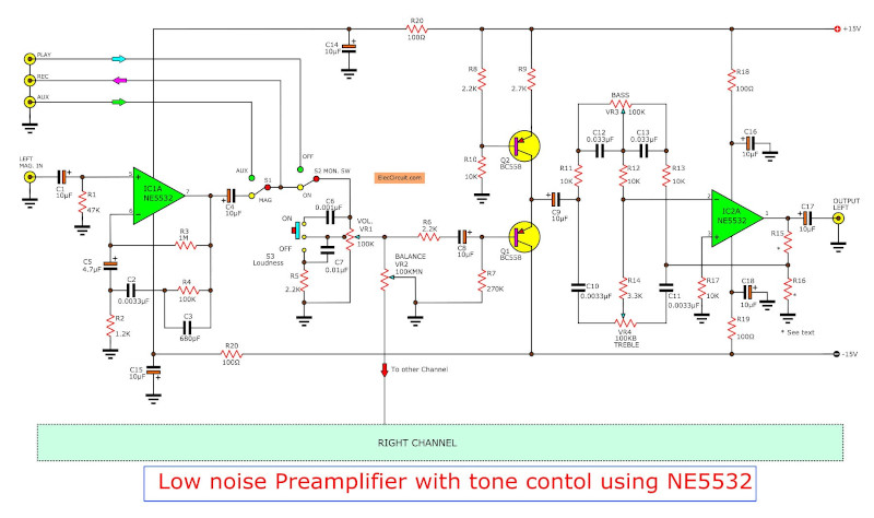
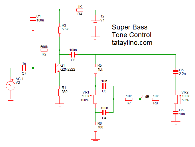
Bass control circuit diagram. And easy to builds with pcb layouts. See more ideas about circuit diagram circuit electronics circuit. Below is the list of circuit diagrams of mono and stereo amplifiers bass and treble used in all amplifier project videos of this website. All the headings of each circuit diagram is designed clickable to watch the related project videos. We have two circuits both transistors op amp as main so smaller but high gain signal. Many tone control circuit it is important circuit for control bass and treble effects in audio output.
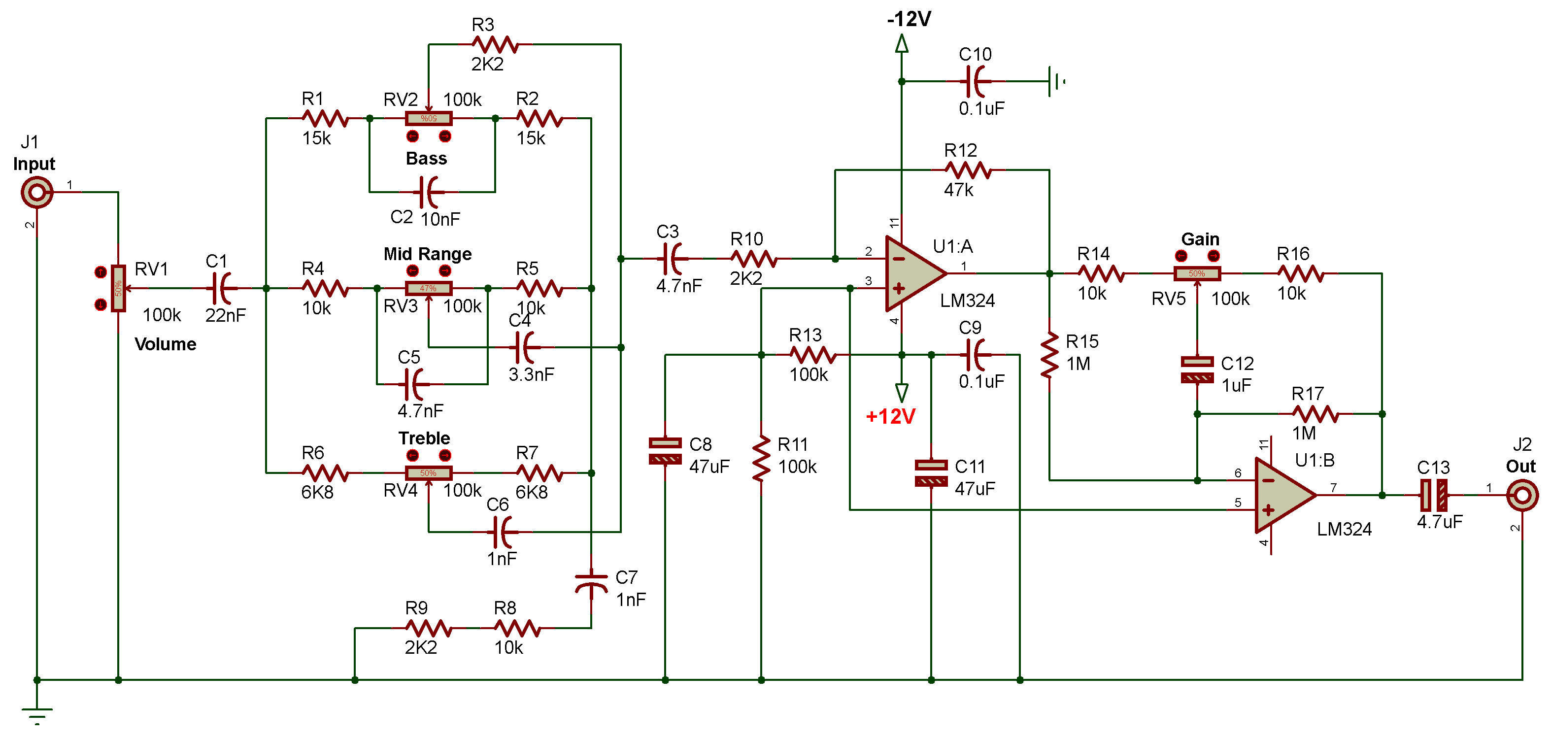
All components you can buy in most of the local markets. All the circuit diagrams are using transistors and ics like c5200 a1943 d718 b688 la4440 etc. Jun 30 2020 explore juni joness board circuit diagram on pinterest. Active tone control circuit using the transistors. Bass booster circuit diagram this bass booster circuit is made using the quad op amp ic lm324. Now i want to suggest you this circuit has 2 forms are.
We have list top 7 tone control circuit which are effective low noise tone control circuit. Talking about the bass treble circuit it is comparatively much simpler and gainful. Circuit description of bass treble circuit. This op amp ic has 4 operational amplifiers but in this circuit only 2 op amps are used. This is bass treble tone control circuit diagram as ideas.


