The disconnecting switch is always placed between the supply line and the starter. Unit 1conclusion this unit explained the basic concepts of motor con trols concentrating on how specialized electrical sym bols words and line diagrams are used to convey information about motor control circuits.
Motor Control Circuit Wiring Eet
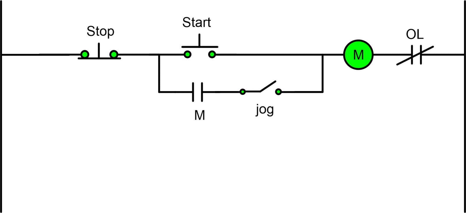
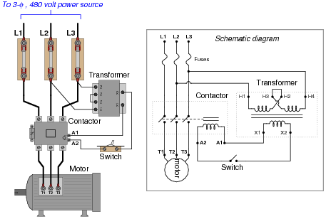
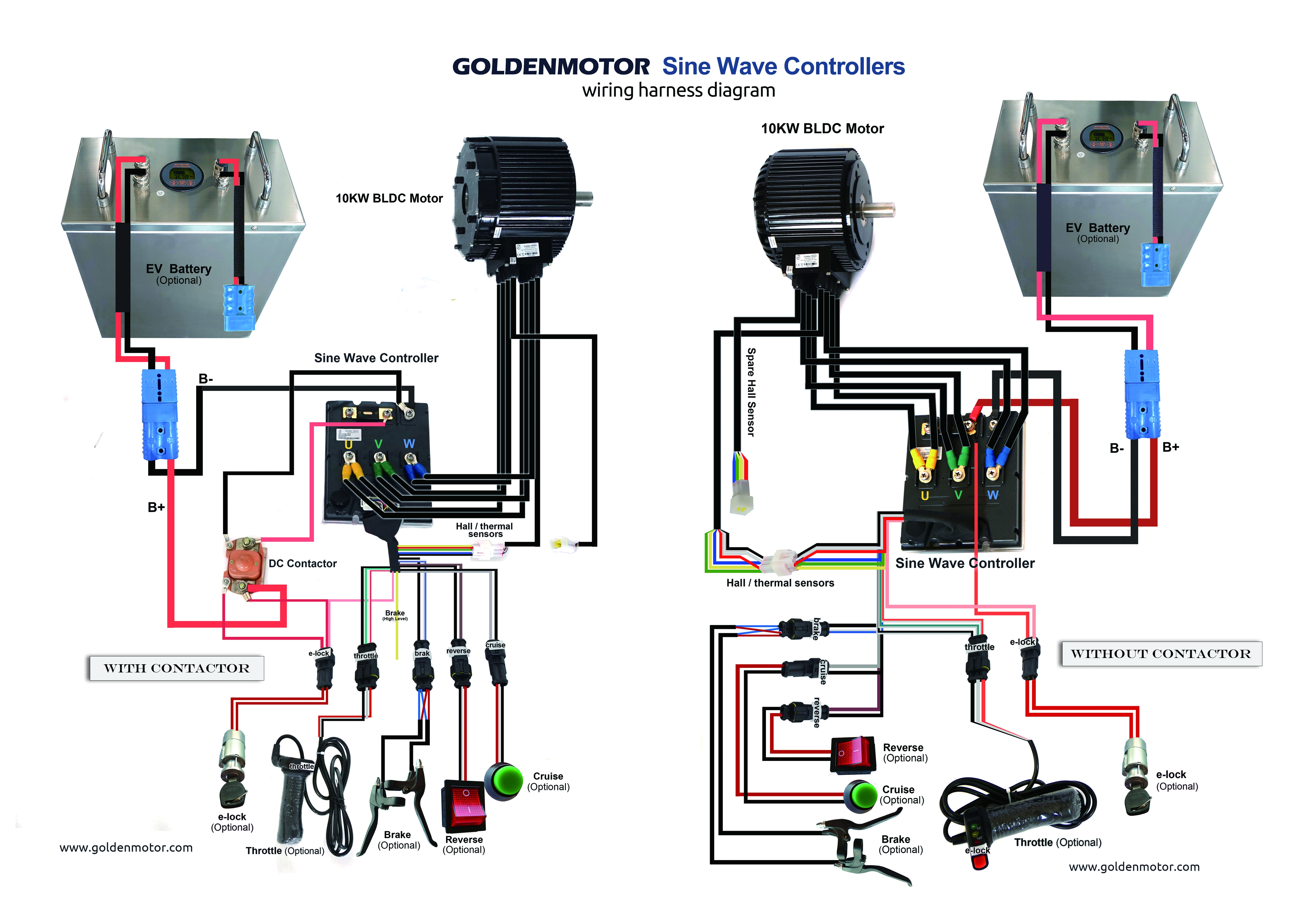
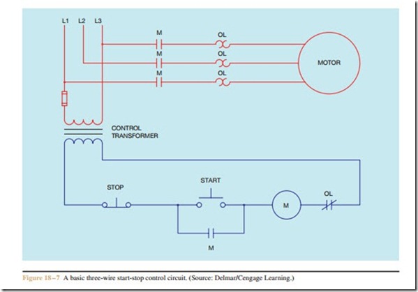
Basic motor control circuit diagram. Starting stopping of 3 phase motor from more than one place power control diagrams. The basic language of control is the circuit diagram. Basic wiring for motor contol language of control circuit diagrams communicate information quickly and efficiently. In this particular case i show a low voltage control circuit and a 3 phase higher voltage motor. On off three phase motor connection power control schematic and. Figure 2 shows a typical line or schematic diagram.
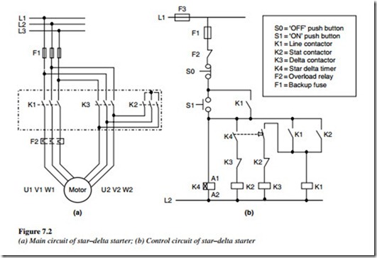
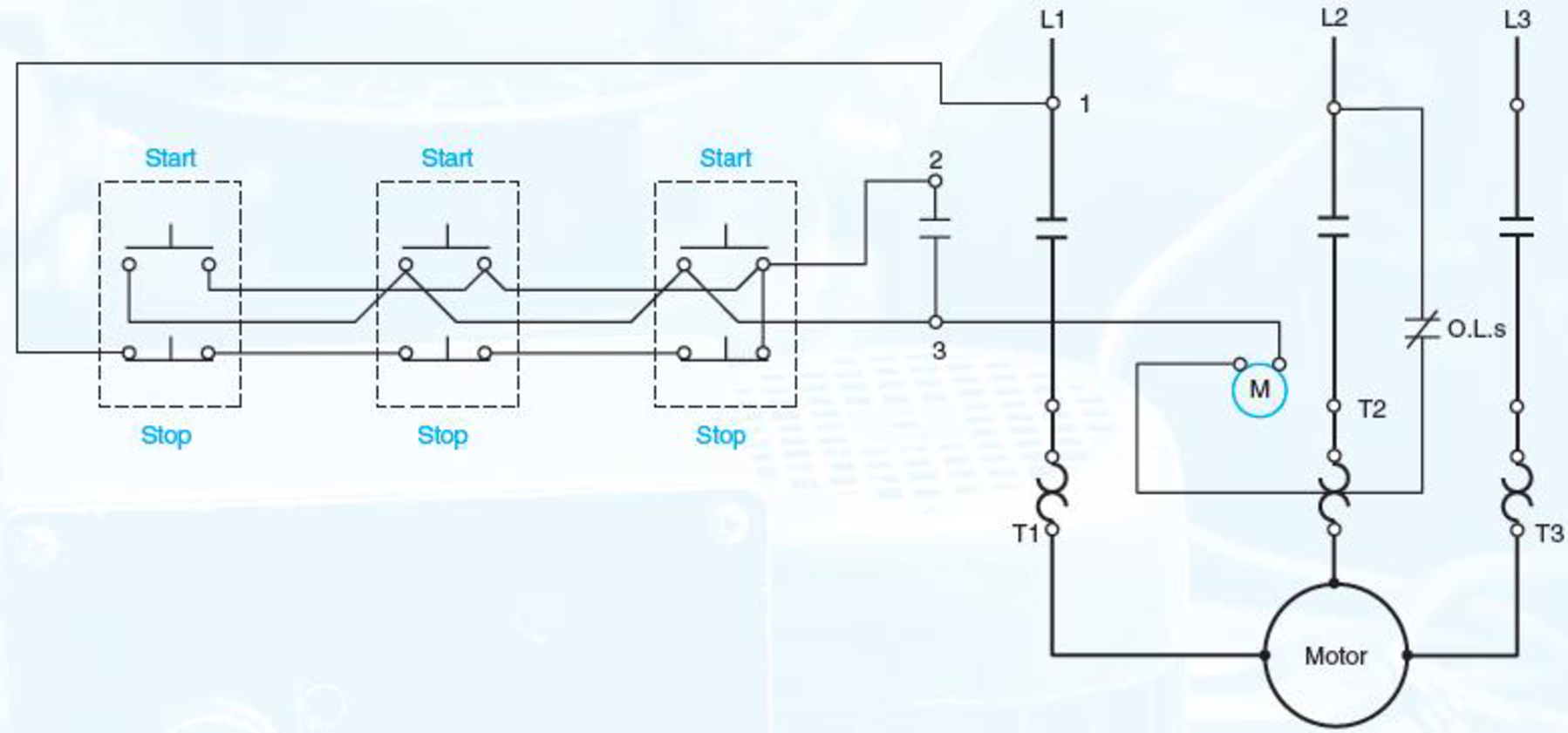
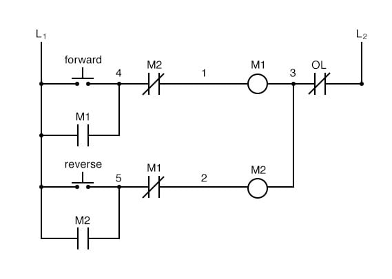
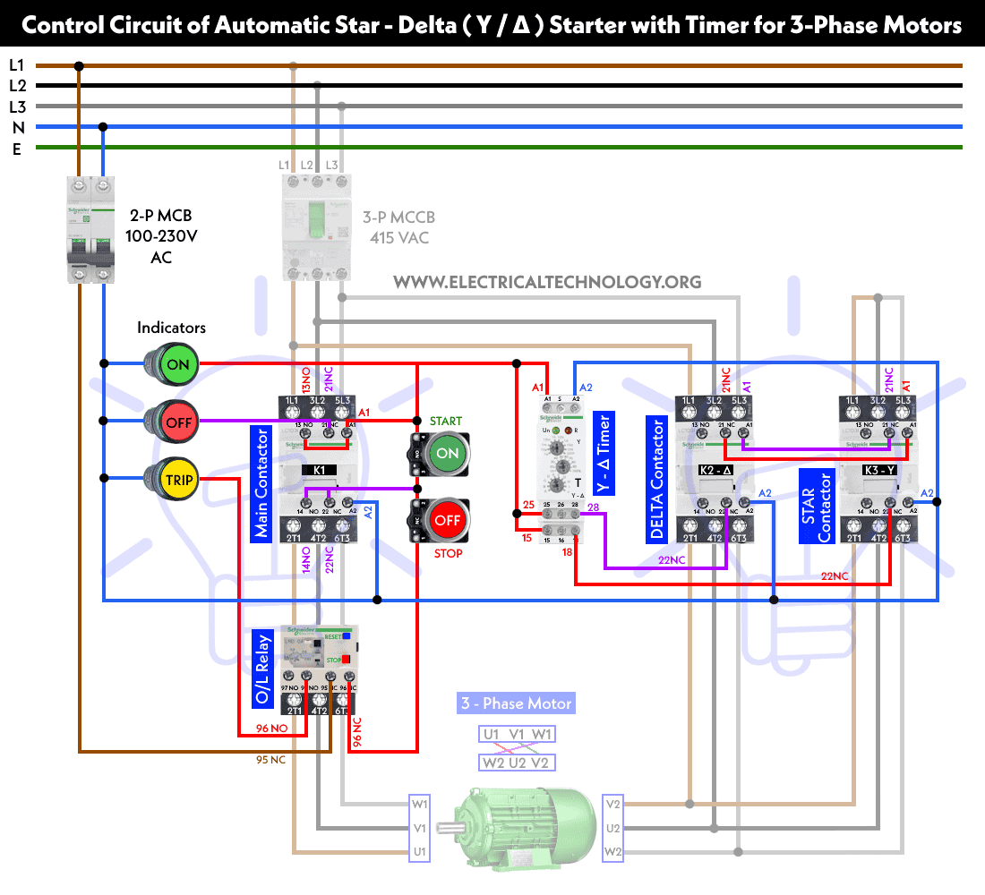
The switch and starter are sometimes mounted in the same enclosure to make a combination starter. Three phase motor connection stardelta y δ reverse forward with timer power control diagram. The manufacturers of motor control equipment for edu cational material and standard motor control circuits. Line diagrams also called schematic or elementary diagrams show the circuits which form the basic operation of the controller. Control 3 phase motor from more than two buttons power control diagrams. They are an ideal means for troubleshooting a circuit.
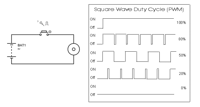
Control circuits can be divided into two major types. They do not indicate the physical relationships of the various components in the controller. A motor control circuit contains two basic components. A two wire control circuit can be a simple switch that makes or breaks connection to a motor figure 18 1. Two wire control circuits and three wire control circuits. A disconnecting switch and a starter.
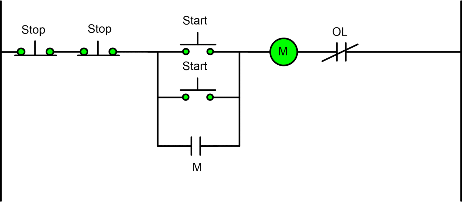
A good example of this type of control is the single phase manual starter shown in figure 3. A very common form of latch circuit is the simple start stop relay circuit used for motor controls whereby a pair of momentary contact pushbutton switches control the operation of an electric motor. Consist ing of a series of symbols interconnected by lines to indicate the flow of current to the various components it tells in.

