If you where not in class this may be confusing. I was tutoring several students with basic wiring this week so i made this video for them to review.

Basic Hvac System Wiring Diagram Fire Liar Slotenmaker
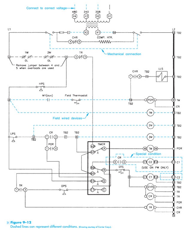
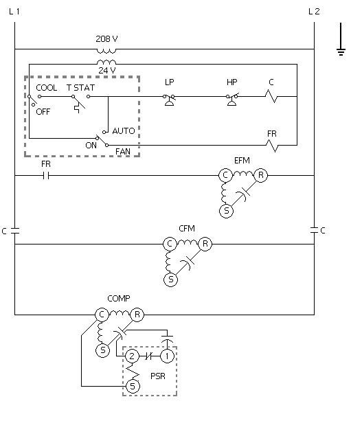
Basic hvac wiring diagram. Also the hvac designer will need to know the size of the electrical loads to assess the impact of the heat generated by the electrical system on the hvac load. Thermostat wiring diagrams for heat pumps heat pump thermostat wire diagrams. Where the power supply is what path the power takes the load component the switch component and a. Heat pumps are different than air conditioners because a heat pump uses the process of refrigeration to heat and coolwhile an air conditioner uses the process of refrigeration to only cool the central air conditioner will usually be paired with a gas furnace an electric furnace or some other method of heating. Because it explains electrical circuits the diagram looks like a ladder which is where the name comes from. It shows how the electrical wires are interconnected and can also show where fixtures and components may be connected to the system.
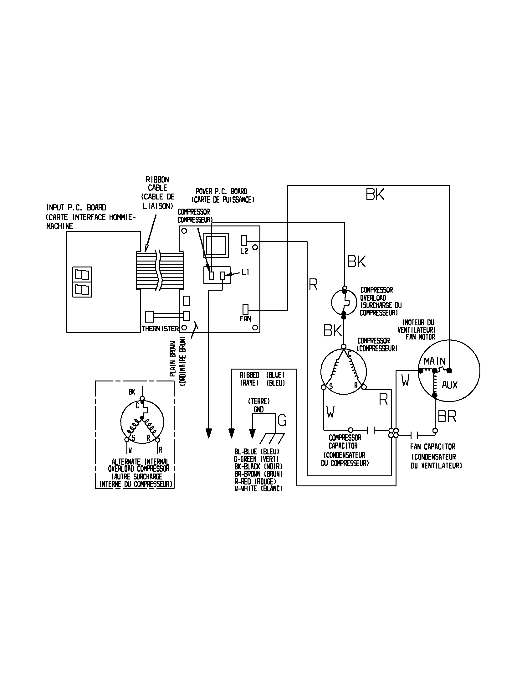
How to read ac or air conditioner condenser unit wiring diagram schematic. I go over 4 ac condenser wiring diagrams and explain how to read them and what all the symbols and charts on the label. Most ladder diagrams show the following basic components. A wiring diagram is a simple visual representation of the physical connections and physical layout of an electrical system or circuit. It is long and dry but covers some of the basics. The above points can be fulfilled by understanding the electrical wiring diagram of individual hvac equipment and of the whole system also.
It lists the circuit connections and electrical wiring for the system.


