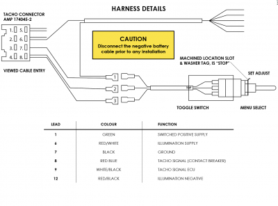
Ammeter distributor starter fuel gage breaker ignition coil light switch dome light tail stop plate instrument lights foot selector switch current voltage regulator generator field gen bat gas tank unit horn button parking lamp sealed beam horn junction block beam. Auto licence to manual qld auto manual ladder diagram auto manual selector switch connection auto to manual conversion shops auto vs manual knife.

Industrial Electronics Troubleshooting Devices Symbols And
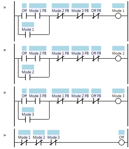
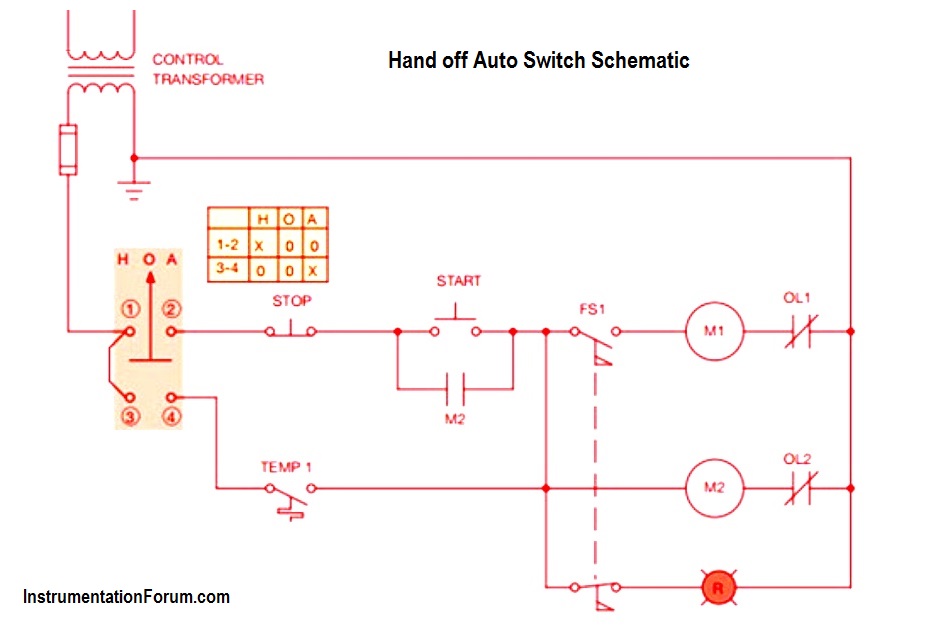
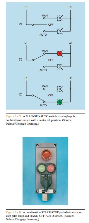
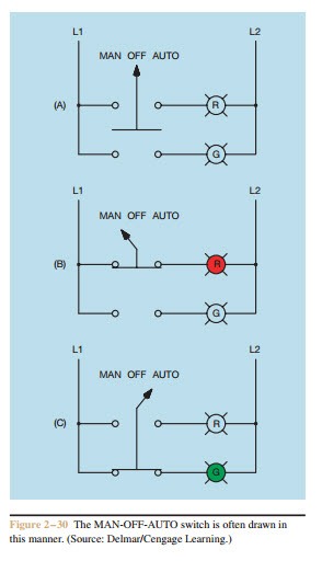
Auto manual selector switch wiring diagram. When the switch is. 2 position selector switch 3 position selector switch 2 position selector push button. Wiring diagram auto electrical wiring diagram drawn by checked date scale sheet no. Hand off automatic controls recognize hand off automatic switches on a schematic diagram. Iron core air core. This is a single pole double throw switch with a center off position as shown in figure 2 29.
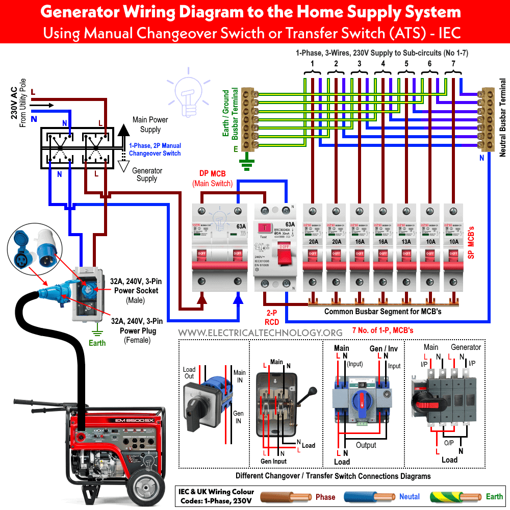
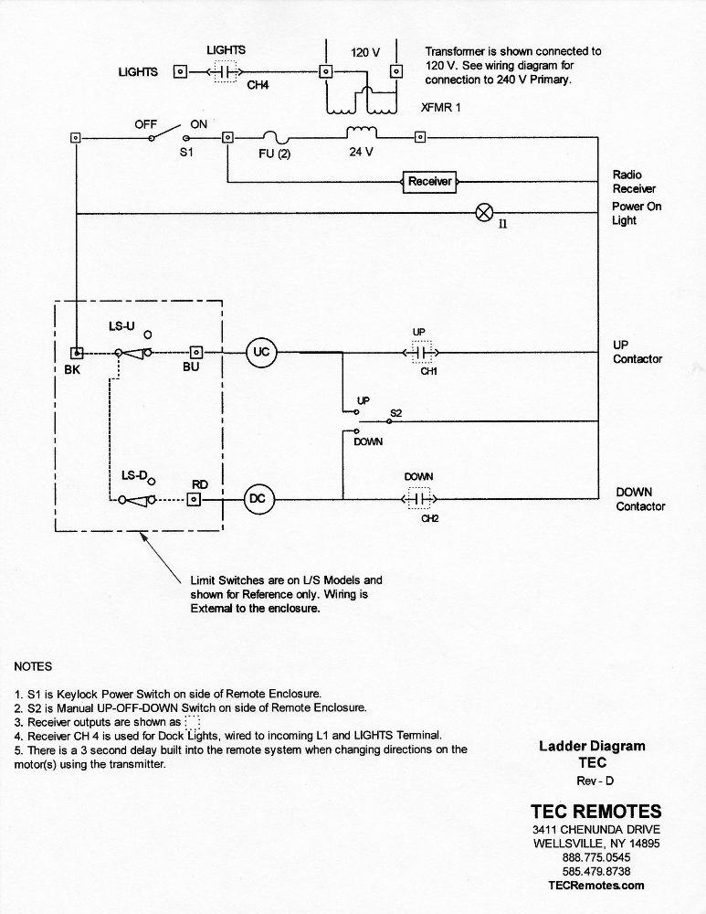
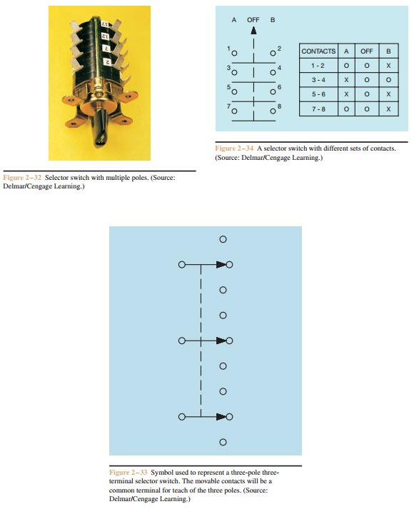
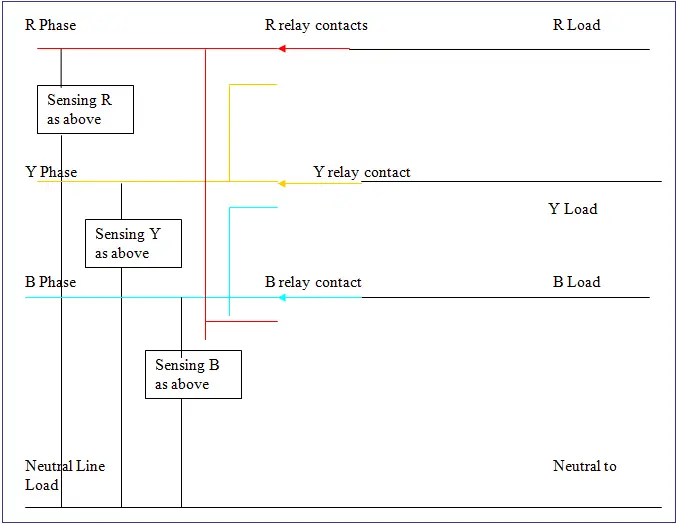
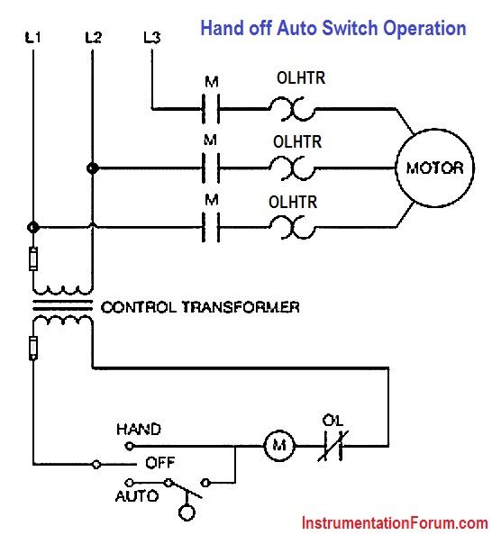
It is also shows the working and operation for different changeover switches wiring connections like single phase manual changeover switch with generator three phase manual transfer switch connection with generator as well as single phase and three phase automatic transfer switches connections to the 1 and 3 phase generators and main fuse board. The circuit shown in figure 271 permits a motor to be operated by a float switch or to be run manually. Learn how this truth table illustrates the manual or automatic contact positions of two contact selector switch. Contact position on a selector switch can easily be illustrated using truth tables. The switch is shown as a single pole. Hand off automatic controls are used to permit an operator to select between automatic or manual operation of a motor.
Man stands for manual and auto stands for automatic. Auto manual switch wiring diagram trane xe900 contactor wiring wiring diagram all share on twitter facebook whatsapp pinterest tags. A very common selector switch is the man off auto switch. Wiring diagram book a1 15 b1 b2 16 18 b3 a2 b1 b3 15 supply voltage 16 18 l m h 2 levels b2 l1 f u 1 460 v f u 2 l2 l3 gnd h1 h3 h2 h4 f u 3 x1a f u 4 f u 5 x2a r power on optional x1 x2115 v 230 v h1 h3 h2 h4 optional connection. Selector switches selector switches are operated by turning a knob instead of pushing a button.
