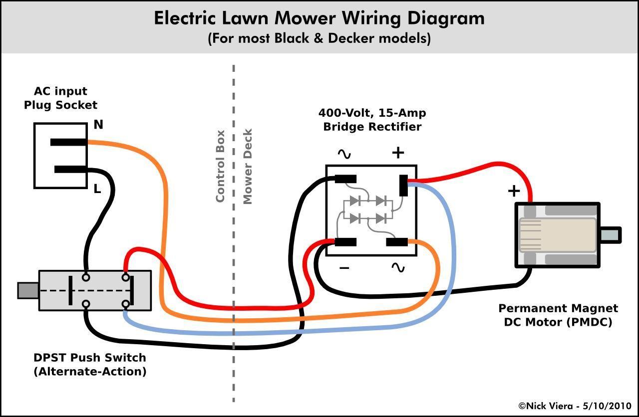
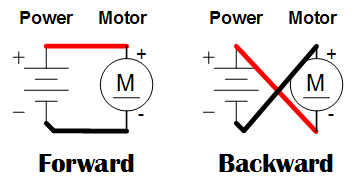
It demonstrates how the electrical wires are adjoined as well as can likewise reveal where fixtures and also components may be. Electric motors can be powered by direct current dc sources such as from batteries motor vehicles.

Different Types Of Electric Motors And Their Applications
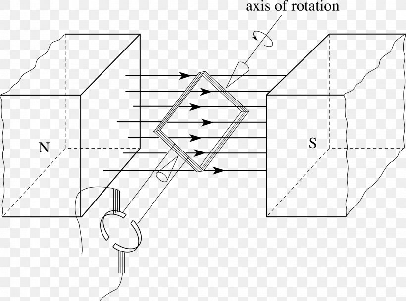
An electric motor diagram. This means the force on each side of the coil is always pushing in the same direction which keeps the coil rotating clockwise. Electric motor wire marking connections. For most shore facility applications this is the case. Just as in the three phase motor diagram the motor shows the power supply lines as being identified with the t. For specific leeson motor connections go to their website and input the leeson catalog in the review box you will find connection data dimensions name plate data etc. A wiring diagram is a simple graph of the physical connections and physical layout of an electrical system or circuit.
Learn the procedures thatll save time during the diagnostic process. In a typical dc motor there are permanent magnets on the outside and a spinning armature on the inside. In many cases the single phase motors on board aplease check my motor wiring diagram mig welding. I found this information about motor mounting dimensions in the same book. An electric motor dimension chart depicting the standard frame sizes of electric motors. The armature contains an electromagnetwhen you run electricity into this electromagnet it creates a.
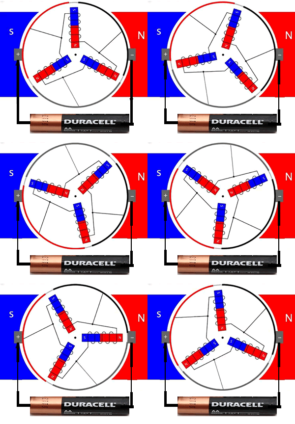
Inside an electric motor these attracting and repelling forces create rotational motion. Note how the commutator reverses the current each time the coil turns halfway. The basic diagram view a shows a circle with two leads labeled t1 and t2. Three phase see below single voltage. The permanent magnets are stationary so they are called the statorthe armature rotates so it is called the rotor. The motor will also have a name plate with information such as the make model horse power rating voltage amperage etc.
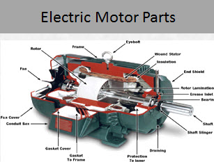
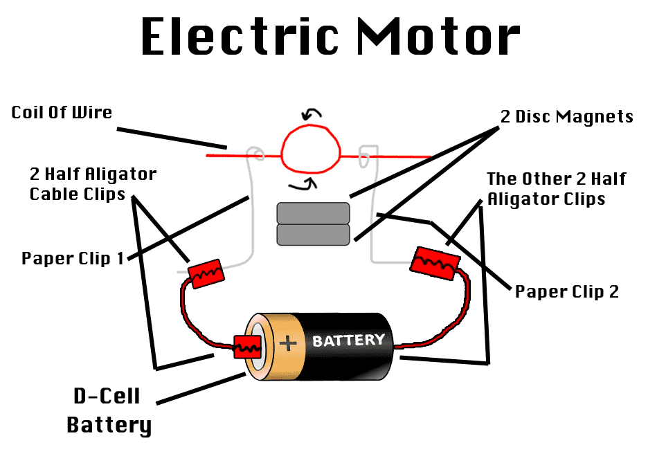
The article how electric motors work explains how brushed motors work. If the motor has a dual voltage capability then it will state 120240 volts and there will be a wiring configuration or wiring connection diagram which will explain the wiring configurations for each voltage. When diagnosing a faulty automotive motor it is often impossible not to perform major disassembly such as the fuel pump itself. An electric motor is an electrical machine that converts electrical energy into mechanical energymost electric motors operate through the interaction between the motors magnetic field and electric current in a wire winding to generate force in the form of torque applied on the motors shaft. A simplified diagram of the parts in an electric motor. Some dc electric motor information below schematic wiring diagram for dc electric motor connections.
The armature or rotor is an electromagnet while the field magnet is a permanent magnet the field magnet could be an electromagnet as well but in most small motors it isnt in order to save. How it works in practice. Electric motor nema c and j face mounting dimensions chart. In the above diagram you can see two magnets in the motor. Baldor electric motor wiring diagram lovely 240v single phase motor just what is a wiring diagram.
