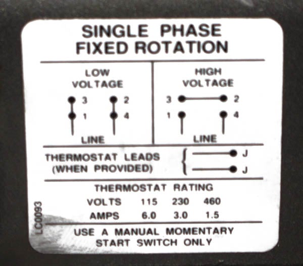
Capacitor motor single phase wiring diagrams always use wiring diagram supplied on motor nameplate. 6 lead motor wiring diagram collections of wiring diagram 2 speed motor 3 phase new two speed motor wiring.
How To Connect 3 Phase Motors In Star And Delta Connection
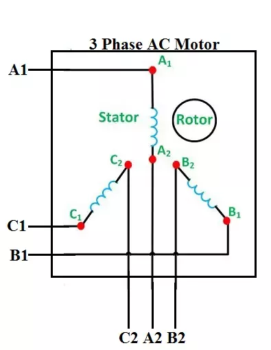
6 wire 3 phase motor wiring diagram. I believe i need to wire u1 v1 w1 to power and leave u2 v2 w2 disconnected. Wye start delta run motor wiring diagram great three phase motor wiring diagram 3 star delta and how to wire a agnitum me. Six wire three phase electric motors are dual voltage motors. Single phase motor wiring diagram pdf wiring diagram collection. The supply voltage is either 240 volts alternating current vac or 480 vac. W2 cj2 ui vi wi w2 cj2 ui vi wi a cow voltage y high voltage z t4 til t12 10 til t4 t5 ali l2 t12 ti blu t2 wht t3org t4 yel t5 blk t6 gry t7 pnk.
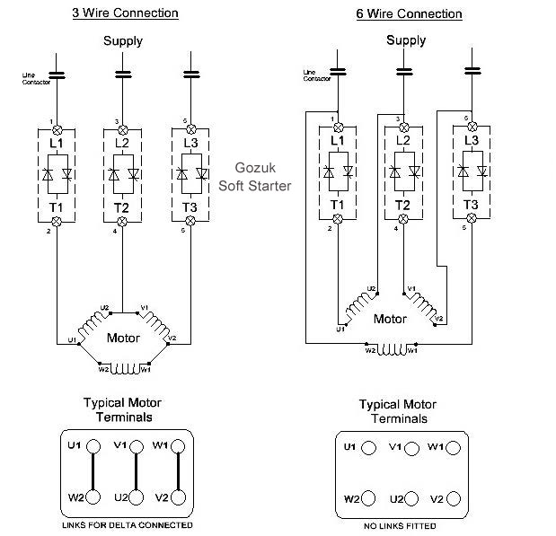
How to wire a baldor 3 phase motor. I am trying to wire up a two speed 6 wire 3 phase motor to. Wiring diagram 6 lead 3 phase 480 volt motor wiring library 3 phase motor wiring diagram 6 wire wiring diagram contains the two examples 3 phase motor wiring diagram 12 leads june 15 2020 wiring diagram by anna r. A three phase motor is more efficient than a single phase motor because of the peculiarities of alternating current ac. Reduced motor cable size. The diagram below illustrates how the motor is connected in 6 wire also known as inside delta.
On a 12 wire motor wired for high voltage ie 480v 10t 11t and 12t must be connected together but not connected to anything else. The major advantage is that the current in the scr is 58 less than it would be for the same motor connected in 3 wire. When a motors power supply is brought in from three wires instead of just one with the power delivery cycling through each of these in sequence hence the a part of ac it permits an effective power level that is 3 times higher about 1728 times higher than a. The other 9 wires would be connected as in a 9 wire motor note in a 9 wire motor the equivalent of t10 t11 and t12 are internally connected together. L1 to t1 l2 to t2 l3 to t3 t4 to t7 t5 to t8 and t6. How the wires are interconnected dictates the voltage being supplied to the motor.
3 phase motor wiring diagram 6 wire. The wiring diagram for connecting thee phase motor to the supply along with control wiring is shown in figure below. Wiring diagram for doorbell lighted help needed 5 hp to cutler and 3. Below is the motor data plate and whats left of the wiring diagram. This is a start stop push button control schematic which includes contactor m overload relay control transformer and push buttons. Now for the purposes.
Wiring may already be present if a startdelta type starter was previously used. The motor will supply the same amount of power but with a different load amperage. How to wire a 3 phase motor and vfd duration. Stepper motor wiring diagram elegant ponent series circuit diagrams.

