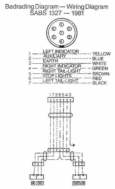
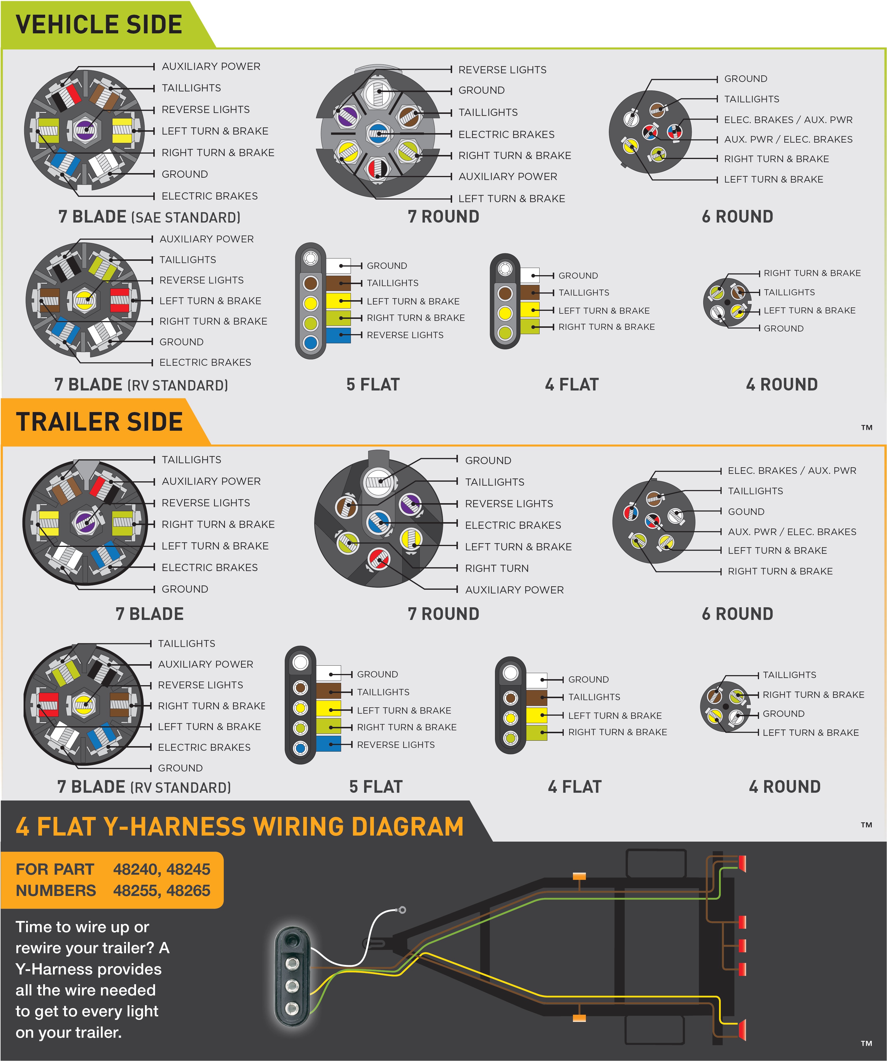
Trailer electrical connectors come in a variety of shapes and sizes. 1 4 wire the first 4 pins white brown yellow green just like the 4 pin connector above.

6 Pin Wiring Diagram For Trailer Wiring Diagrams Dat
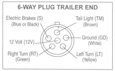
6 pin trailer wiring diagram with brakes. 34 inch by 1 inch 6 way rectangle connectors right turn signal green left turn signal yellow taillight brown ground white. By law trailer lighting must be connected into the tow vehicles wiring system to provide trailer running lights turn signals and brake lights. 6 pin trailer wiring diagram with brakes 6 pin trailer wiring diagram with brakes people comprehend that trailer is a car comprised of rather complicated mechanisms. 6 way wiring is most common on gooseneck trailers and allows for use with a brake controller. I have included a help article on trailer wiring that includes a diagram and wiring matrix that explains wire color function and gauge needed among other helpful information. There is a suggested and common method for 6 function trailer wiring.
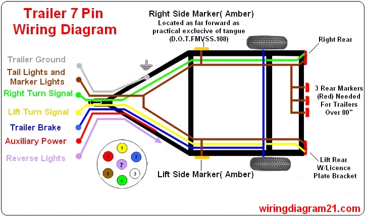
7 pin trailer wiring diagram with brakes 7 pin flat trailer wiring diagram with brakes 7 pin rv trailer wiring diagram with brakes 7 pin trailer wiring diagram with brakes every electrical arrangement is made up of various different parts. 6 pin trailer wiring introduces two new functions a wire for connecting trailer brakes and a wire for 12 volt auxiliary power. Can also be used as custom wiring on trailers with 3 lightwire systems. When it is plugged it disengages hydraulic trailer actuator when you reverse so the trailer brakes are off at that moment. The basic purpose remains the same whether your truck and trailer is using a 4 way 5 way 6 way or 7 way connector. Use on a small motorcycle trailer snowmobile trailer or utility trailer.
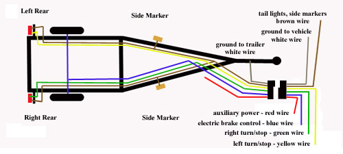
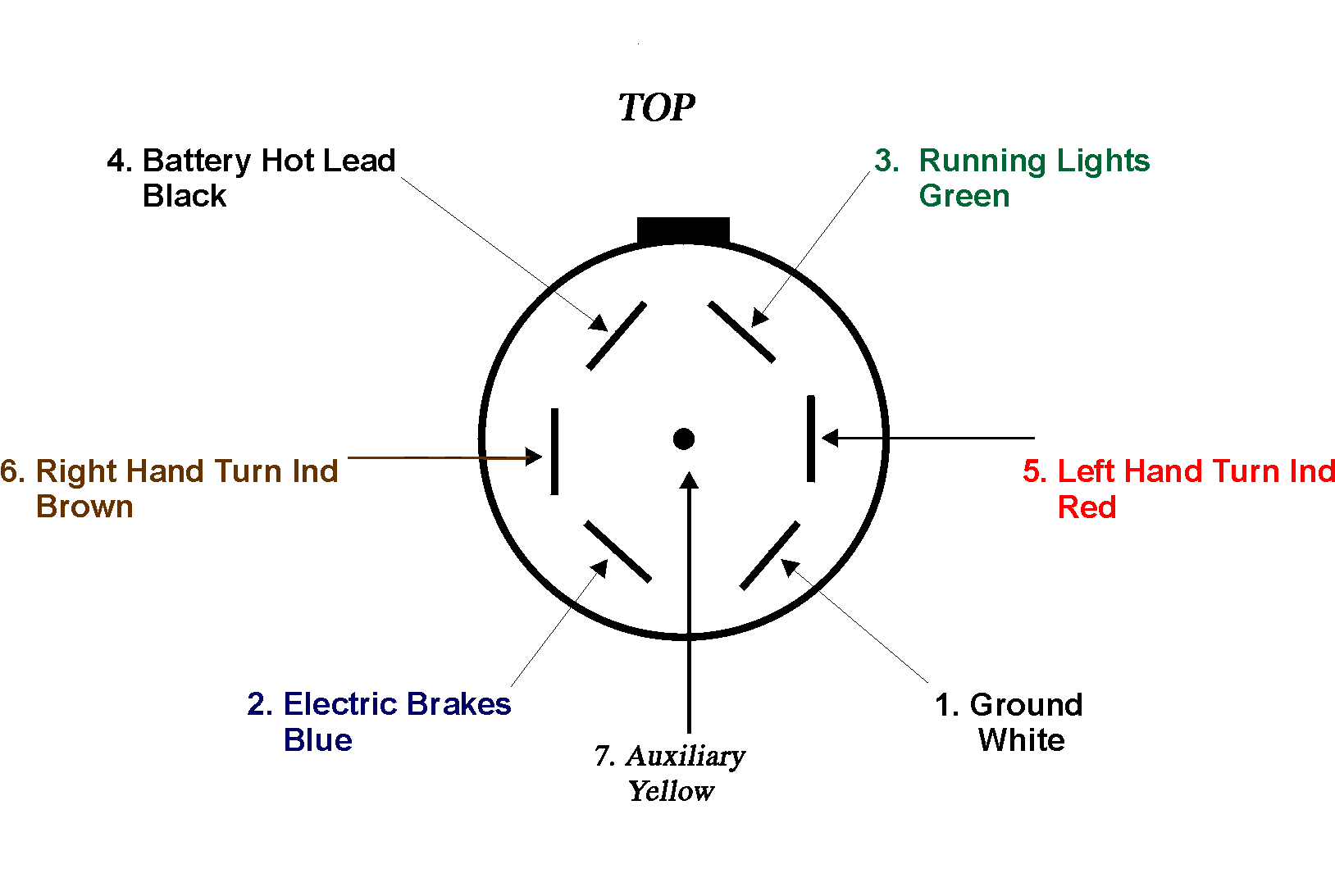
The red and blue wire can be used for brake control or auxiliary. Right turn left turn ground tailmarker brake battery. You will have the following functions. This vehicle is designed not just to travel one location to another but also to carry heavy loads. Trailer wiring diagram 6 pin round 6 way trailer connectors are used in the following vehicle applications. Traditional trailer with brakes use a 5 pin connector.
The extra wire as a rule is used to power backup lights. Trailer wiring diagrams trailer wiring connectors various connectors are available from four to seven pins that allow for the transfer of power for the lighting as well as auxiliary functions such as an electric trailer brake controller backup lights or a 12v power supply for a winch or interior trailer lights. Blue electric brakes or hydraulic reverse disable see blue wire notes below in the trailer wiring diagram and connector application chart below use the first 5 pins and ignore the rest. A wiring diagram is a type of schematic which makes use of abstract photographic signs to show all the interconnections of components in a system. Each component ought to be set and connected with different parts in particular manner. 6 pin trailer connector wiring diagram whats wiring diagram.
If not the arrangement will not function as it ought to be.


