Click on picture for larger view. This is essential to.

Wiring Diagram Required For Rotary Cam Changeover Switch
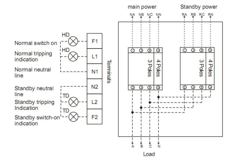
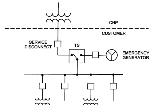
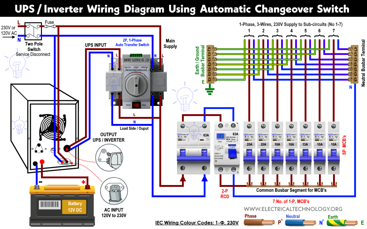
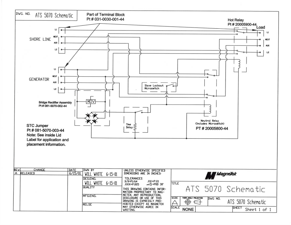
4 pole transfer switch wiring diagram. There is no neutral to ground link at the generator. Using a 3 pole transfer switch next consider adding a 3 pole ats and a generator to the aforementioned simple circuit see figure 3. Manual changeover switch wiring diagram as you know that we use generator as emergency power source in our house wiring we can do the generator changeover system in two methods in which one is manual and 2nd one automatic system. By design it is a physical impossibility for both power sources to supply the load simultaneously unless of course that is the intent. In its most basic form a transfer switch for a 120240v single phase service is simply a double pole double throw switch of proper ampere rating with a middle off position fig. 3 pole and 4 pole transfer switch switching characteristics abstract whether to and how to switch a neutral connection when transferring a load between two separate three phase sources is a topic of frequent discussion 123456.
Keep in mind that a 3 pole transfer switch with overlapping neutral contacts is not considered a true 4 pole switch according to the nec and ul 1008. This diagram illustrates wiring for one switch to control 2 or more lights. The source is at sw1 and 2 wire cable runs from there to the fixtures. Many systems do not switch the neutral wire and tie the three neutral wires together. Multiple light wiring diagram. Figure 4 wiring diagram of a manual transfer switch in the off position figure 5 wiring diagram of a manual transfer switch in the on.
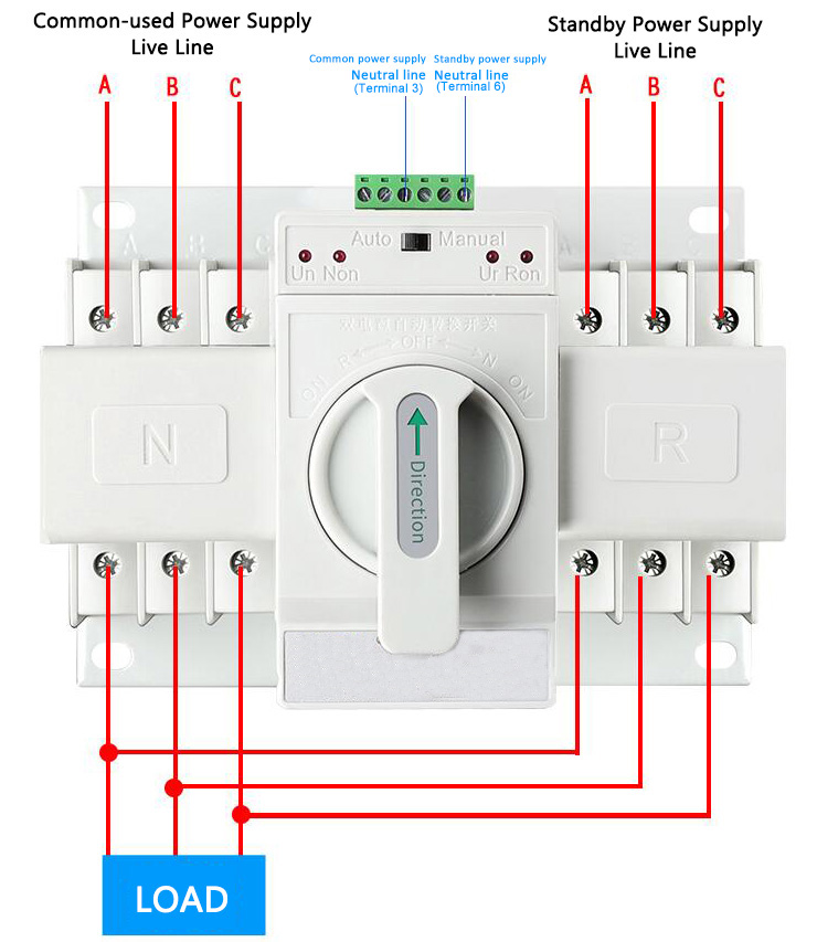
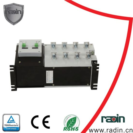
Asco is the global leader in critical power transfer switch technology. This type of automatic transfer switch offers the following benefits. Selecting between a three pole or four pole ats 5 final thoughts while there are many factors that determine whether to use a three or four pole transfer switch it should be emphasized that in systems with more than one ats it is important to use the same ats configuration three or four pole throughout the system. Asco switches transfer both low and medium voltage loads up to 4000 amps. Should a three pole or four pole switch be used. The upper portion of the changeover switch is directly connected to the main power supply while the lower first and right connections slots are connected to the backup power supply like generator or inverter.
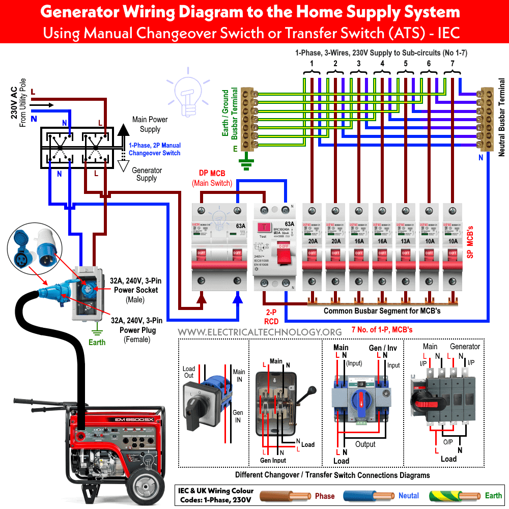
In fig 2 different connection and wiring diagrams are shown for a two pole single phase manual changeover switch. Verify the method of wiring with your transfer switch and generator before installation. Because there is now a 3 pole ats in this system the neutral is continuous and the generator is not considered to be a separately derived source. The hot and neutral terminals on each fixture are spliced with a pigtail to the circuit wires which then continue on to the next light.


