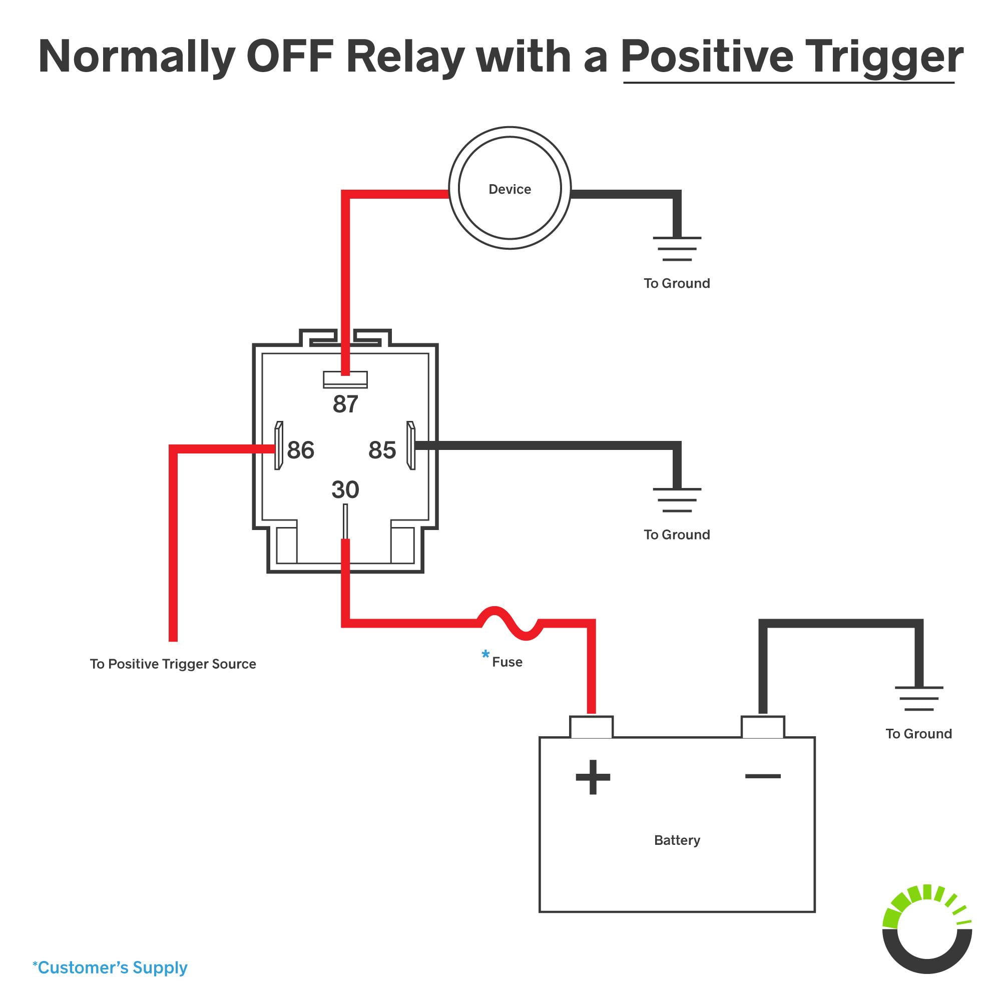
Well since i had an idea but wasnt 100 sure i did some reading and decided to do a quick vid. The iso defines this type of relay as 1 inch 25 cm by 1 inch 25 cm by 05 inches 254 mm by 254 mm by 127 mm.

Wiring Car Spotlights Diagram H1 Wiring Diagram
4 pin relay spotlight wiring diagram. If the contact is broken with the relay at rest then the relay is referred to as normally open no and if. This video covers both 4 and 5 pin 12vdc relays. How to wire your light using a relay the relay will have 4 points on it marked 30 87 85 and 86. 12 volt wiring diagram best 12v relay pin 5 and roc grp org in. In this video i show you how to wire a 12 volt automotive bosch style relay. 40 amp 4 pin relay wiring diagram on 40 images.
These layouts are shown on the two 5 pin relays below pin 87a not present on 4 pin relays. This fuse will protect the spotlight and the relay from surges if there is an issue with your electrical system. Best bosch relay wiring diagram 5 pole electrical outlet symbol 2018. As in the diagram a wire is run from a 12 volt power source to the switch in the cab and out to the relay placing a fuse at the source of the power. This 4 pin relay comes with no labeling or wiring diagram. The iso mini relay we have looked at above has 4 pins or terminals on the body and is referred to as a make break relay because there is one high current circuit and a contact that is either open or closed depending upon whether the relay is at rest or energised.
An iso micro relay has the control circuit connected to pin 86 and pin 85 and the load circuit connected to pin 30 and pin 87 or 87a. I never write reviews but i figured this would be a good one since i researched hi and low to figure out how to wire. Hvac fan relay wiring diagram download. Wiring the spotlight using a relay. Follow the relays wiring schematic when connecting the wires to the relay one of the relays terminals goes to ground. The diagram below shows a simple wiring diagram for connecting spotlights to work together with your high beams.
The left side is the pin out of the point is sticking out from at the bottom and the the right side is showing a schematic representation of the relay circuitry. I hope it. The fuse will blow out if too much power flows through it cutting the power and preventing a fire. A few people have asked what gets connected to the different connectors on a relay. So if youd like to get these. All you need is some wire and lugs a 12v 4 pole relay and two fuse holders with the correct fuses.
There will be only 1 second load pin 87 or 87a not both. 12 volt relay wiring diagram collections of best relay wiring diagram 5 pin bosch endearing enchanting blurts. That is kind of cryptic isnt it. Connect the fuse to the positive terminal on the battery. 30 and 87 create the switch to your lights.


