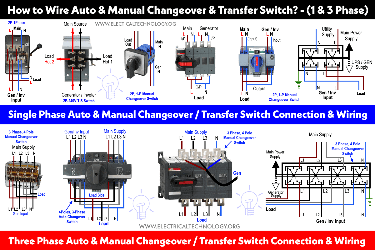
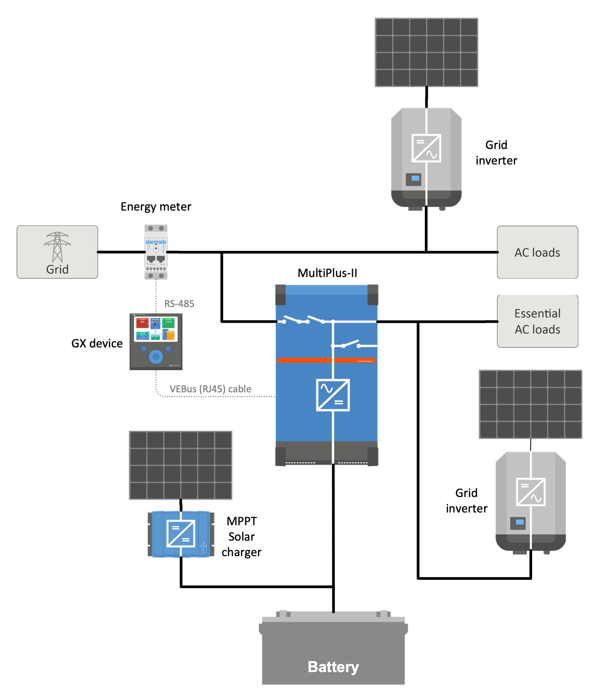
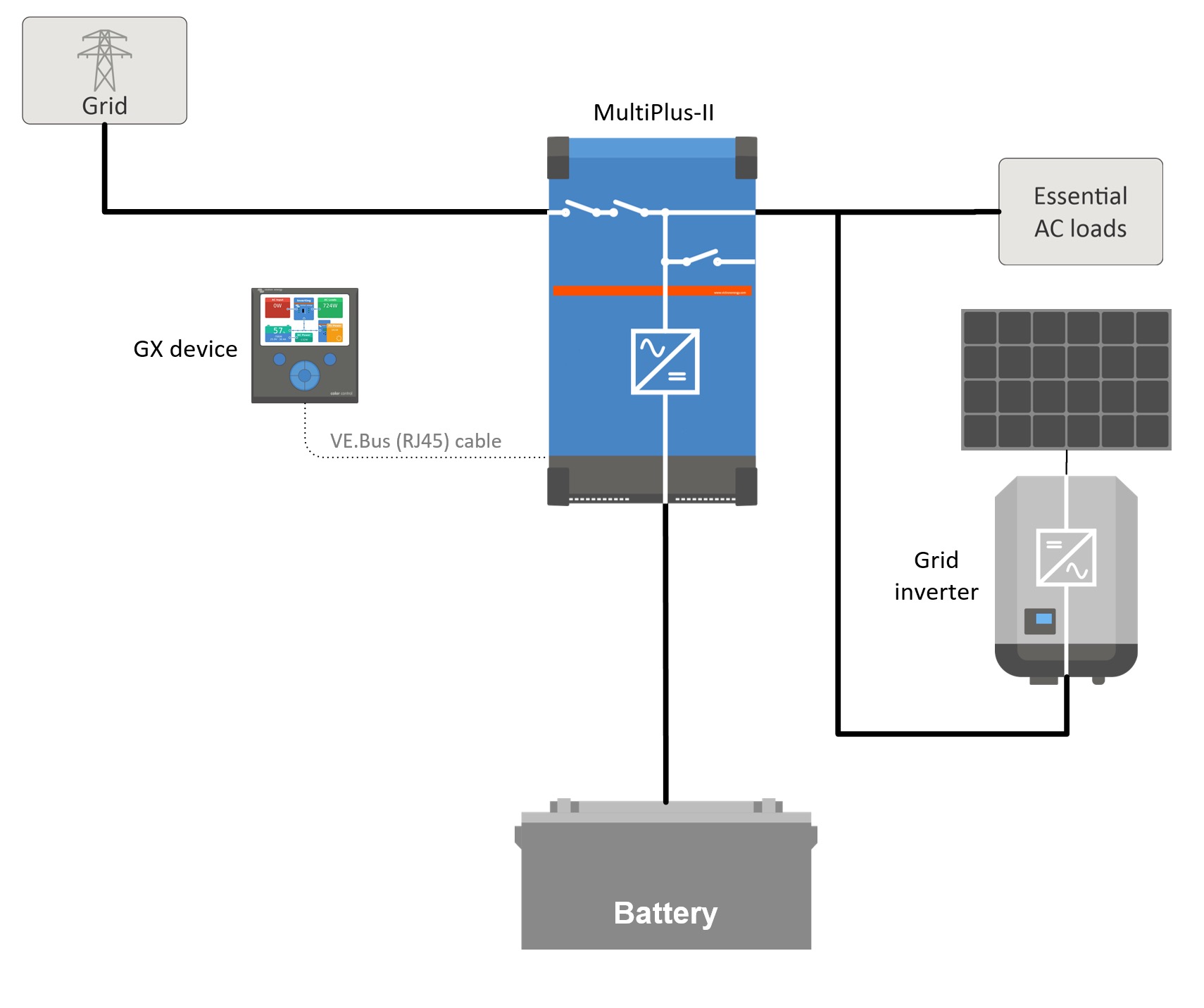
In this methods of wiring the battery and ups has been connected directly to the main supply where the output of the ups has been connected to the partial load specific appliances where we need continues power supply in case of power failure with the help of two pole single phase manual changeover switch. Figure 3 1 operating the switch manually to disable the manual and at the same time also electrical operation turn the handle to the position o and attach the padlock to the handle.
3 Way Switch Wiring Diagram Variations Science Project
3 phase manual changeover switch wiring diagram pdf. As you know that i already published a post and diagram about the manual changeover switch wiring diagram single phase with complete installation and wiring connection method. 32asinglepolen mco32s 32 panelwallmounted 3 manualchangeover40asinglepolen mco40s. 720 copper wire a few meters 7. Figure 3 2 locking the manual operation. 1 cm and 5mm thick mdf board 2. Phase indicator lamps ryb 3 6.
Following materials were used. 3attach the handle to the switch panel by pressing it to the changeover switch until is clicks into place. 0 230 v digital voltmeter 1 5. Author in 3 proposed and implemented an automatic phase change over switch to disconnect load from its power source and transfer it to a standby source say generator in case there is a power. Electricalonline4u a platform to learn electrical wiring single phase 3 phase wiring controlling hvac electrical installation electrical diagrams. Changeover switch 51 16a 100a 4 poles main switch wiring diagram 52 125a3200a main switch wiring diagram 5 connection diagram normal power supply standby power supply load output terminal special attention should be paid to the sequence of connection secondary connection diagram normal power supply standby power supply.
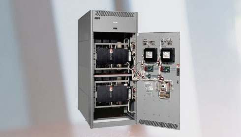
Changeover switch mounted in a metal enclsoure only. 63 amp rated 3 terminal connectors 2 4. 63 amp 4 pole changeover switch on load type 3 its lt make model number was not mentioned anywhere 3. The left side four slots connection points are connected to the load then. 3 phase manual changeover switch wiring diagram or three phase manual transfer switch wiring diagram. Energy meters etc 3 surge arraestors 4 extended busbar links 5 extra cable compartment for extra cables 6 control wiring single phase sno itemdescription model imaxamps mountingstyle.
Manual changeover switch wiring diagram for portable generator or how to connect a generator to house wiring with changeover transfer switch. The three phase utility power as l 1 l 2 l 3 n are directly connected to the upper side of manual changeover switch while the backup power of three phase generator is connected to the first four right slots of at lower side. A toggle switch for switching on off the voltmeter 1 5.


