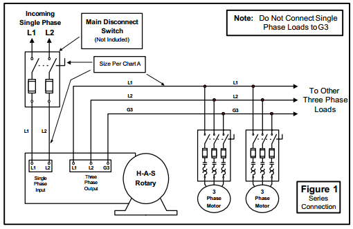
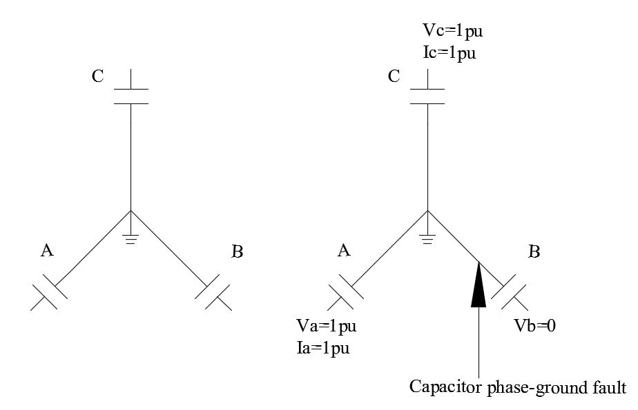
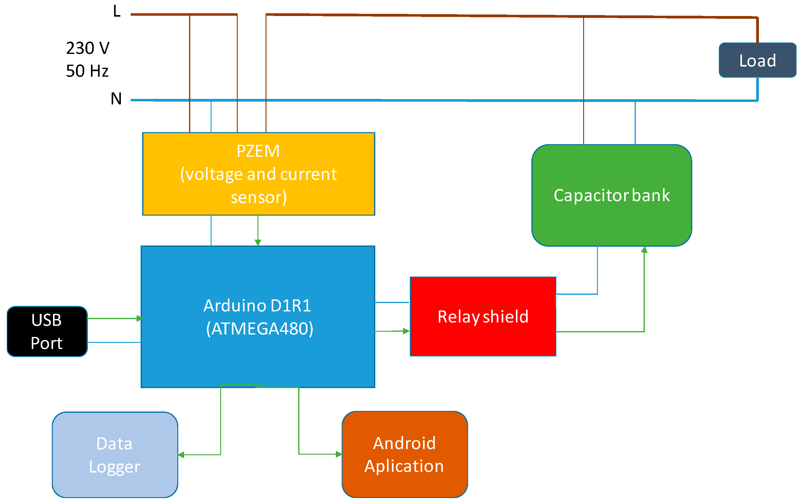
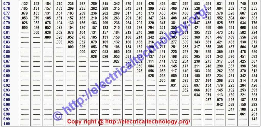
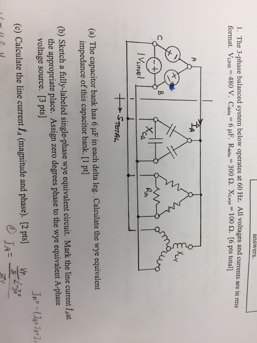
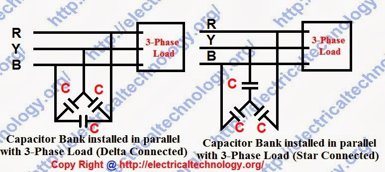
Capacitor bank testing procedure capacitor bank functioncapacitor bank wiring diagram edison world. All these are connected in delta.

Providing Capacitive Reactive Compensation With Shunt
3 phase capacitor bank wiring diagram. The terminals 246 of each disconnector are connected to the three phase reactor d1 d6. It shows the elements of the circuit as simplified shapes and the power as well as signal links between the gadgets. 3 phase capacitor bank wiring diagram. Assortment of 3 phase capacitor bank wiring diagram. Capacitors units should not give less than 100 and more than 115 of rated reactive power at rated. In the delta the line voltage is equal to the.
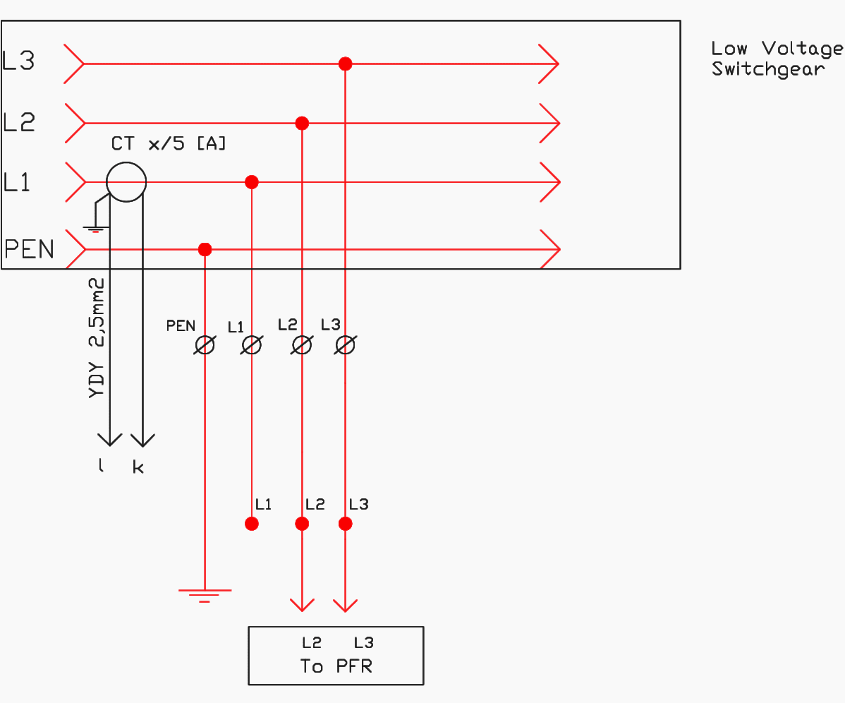
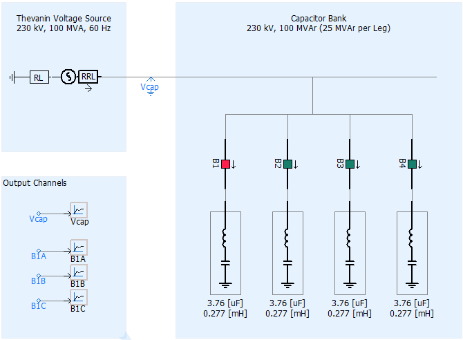
Wiring of capacitor bank control circuit click to expand scheme. Ac fancompressor not working how to test repair broken hvac run start capacitor air condition hd duration. As shown in the above figure 2 capacitor banks have been connected to the grid. Collection of 3 phase capacitor bank wiring diagram. One obtains complete control circuit diagram for the capacitor bank. Each reactor has thermal protection.
A wiring diagram is a simplified conventional pictorial depiction of an electric circuit. An unbalance protection device current relay and transformer continuously monitors the unbalance current between two neutral points and in the event of faults in a capacitor opens the bank control. It reveals the elements of the circuit as streamlined forms and also the power as well as signal links in between the tools. Capacitor units should be capable of continuous operation up to 110 of rated terminal rms 5 voltage and a crest peak voltage not exceeding 2 x 2 of rated rms voltage including harmonics but excluding transientsthe capacitor should also be able to carry 135 of nominal current. 3 phase capacitor bank wiring diagram wiring diagram is a simplified customary pictorial representation of an electrical circuitit shows the components of the circuit as simplified shapes and the aptitude and signal friends amongst the devices. Power factor capacitor bank connection diagramhow to connect three phase power factor.
A wiring diagram is a simplified standard pictorial depiction of an electric circuit. This type of wiring is suitable for banks of all powers and voltages in this case single phase capacitors are subjected to a single voltage. Three phase capacitor bank wiring diagram. Richard lloyd 2738688 views. The wiring diagram of the three phase capacitor bank is shown below.

