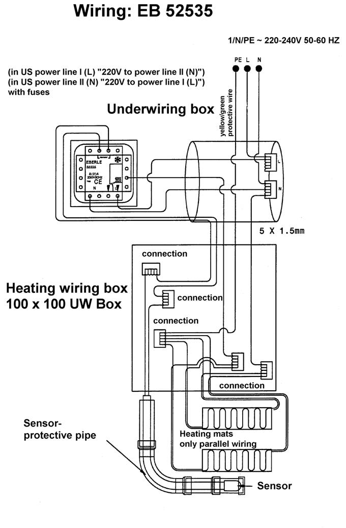
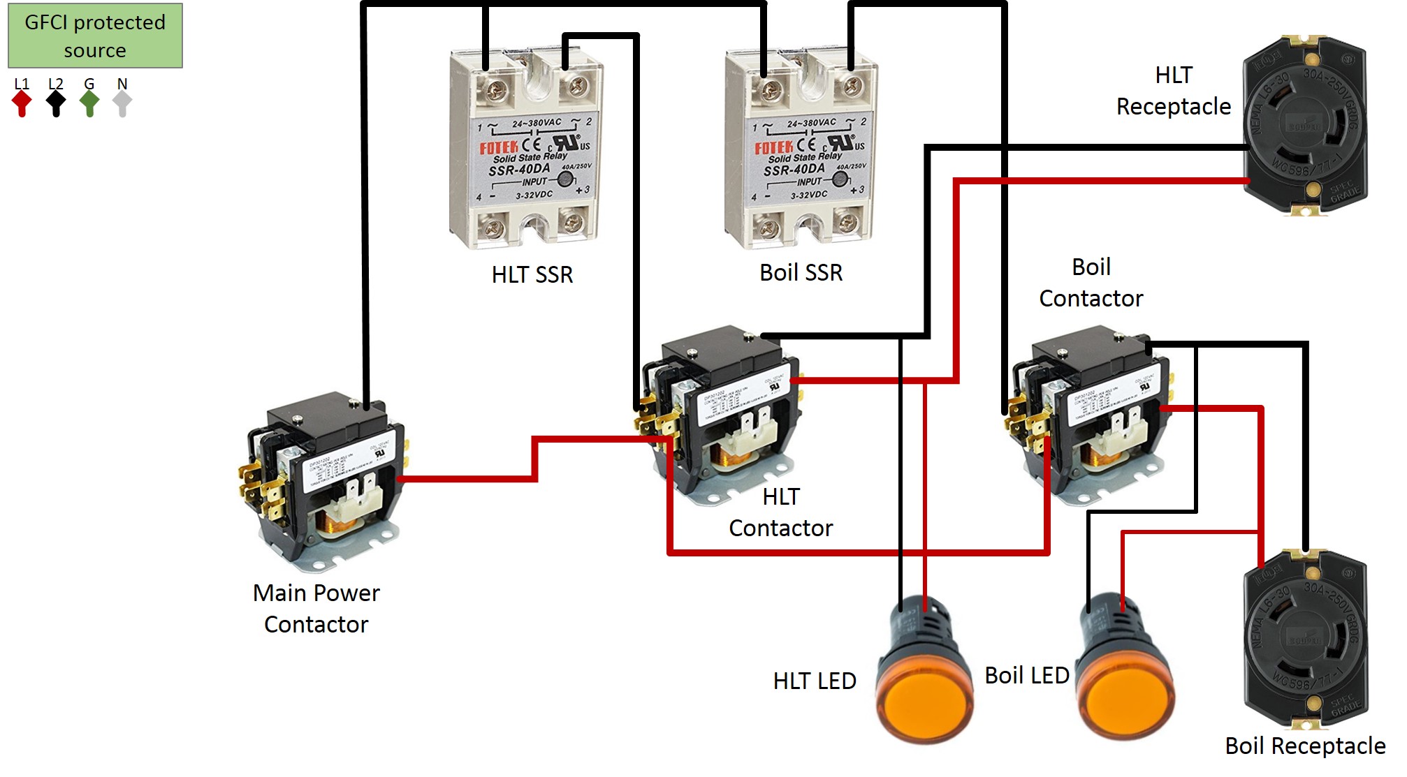
How to wire a contactor. It shows the elements of the circuit as simplified forms and the power and also signal connections between the tools.

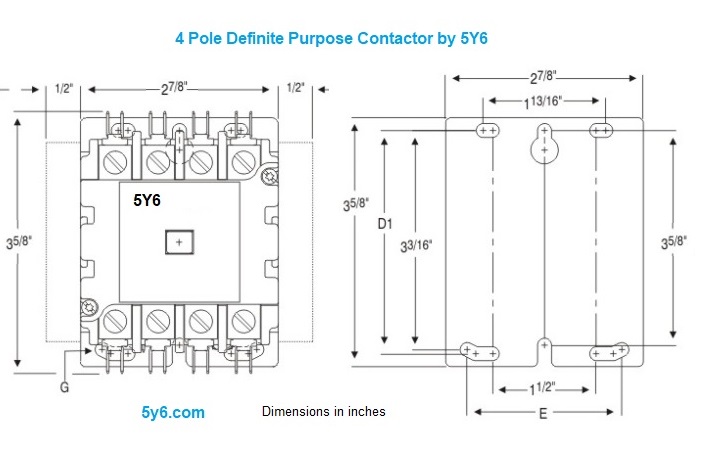
Lighting Contactor 30a 40a 50a 3 4 Pole Electrodepot
240v contactor wiring diagram. Each part should be set and connected with different parts in particular way. Wiring a 20 amp 240 volt switch can be a confusing experience for the average homeowner used to working with standard 110 volt circuits. Single phase power is typically reserved for lower power requirements however in some cases powering a small motor with single phase input power is practical. You will be in a position to understand exactly once the assignments ought to be completed that makes it much simpler to suit your needs to correctly. A wiring diagram is a simplified traditional photographic depiction of an electrical circuit. These lines far exceed the 120 volts ac standard in most homes.
With both conductors carrying 120 volts there is an increased risk of injury or property damage. Collection of contactor wiring diagram ac unit. Variety of 2 pole contactor wiring diagram. 240 volt contactor wiring diagram 220 volt contactor wiring diagram 240 volt coil contactor wiring diagram 240 volt contactor wiring diagram every electrical arrangement consists of various distinct pieces. 240 volts ac and 480 volts ac are commonly used for these large pieces of. This switch doesnt use a neutral conductor.
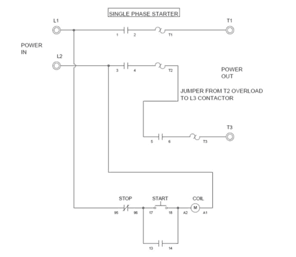
Posted january 18 2018 by springercontrols. If not the arrangement wont function as it ought to be. Home about us news wiring a single phase motor through a 3 phase contactor. The following diagram depicts 3 phase non reversing motor control with 24 vdc control voltage and manual operation. For one thing both supply wires for this switch carry voltage. It reveals the components of the circuit as streamlined forms and the power and signal links in between the tools.
Many large pieces of equipment are powered directly from high voltage lines. Additionally wiring diagram provides you with the time body in which the assignments are for being finished. Contactor wiring diagram wiring diagrams lose contactor wiring diagram. We will use a contactor an auxiliary contact block an overload relay a normally open start pushbutton a normally closed stop pushbutton and a power supply with a fuse. A wiring diagram is a simplified standard pictorial depiction of an electric circuit. Wiring a single phase motor through a 3 phase contactor.


