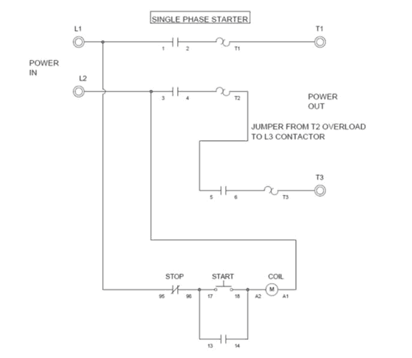
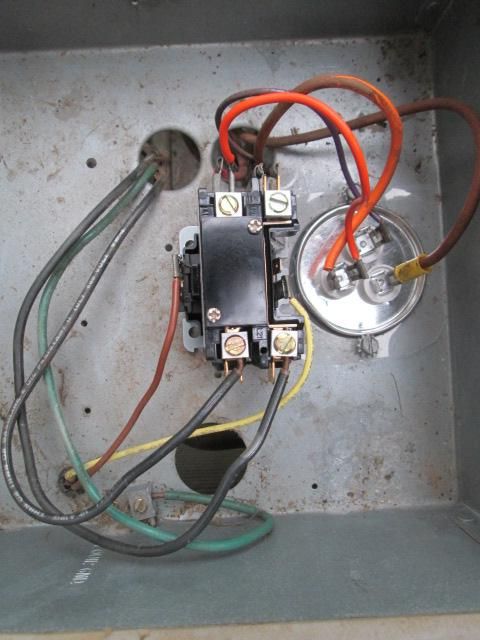
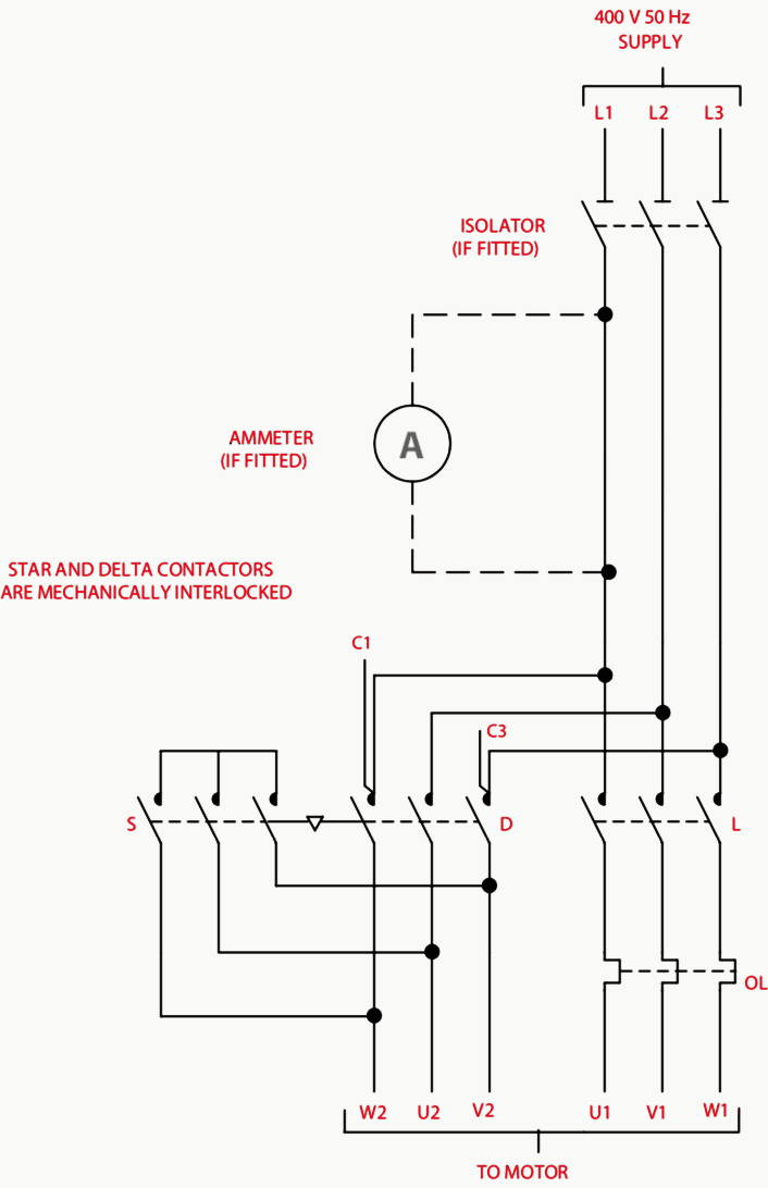
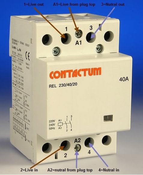
How to wire a contactor. 240 volt contactor wiring diagram you will need a comprehensive professional and easy to know wiring diagram.

Wiring A Contactor Switch Librar Wiring 101
240 volt contactor wiring diagram. Many large pieces of equipment are powered directly from high voltage lines. The contactor then uses the set of conductive discs the contacts to supply a 240 vac power source to something like an air conditioner unit or an air compressor. 240 volt contactor wiring diagram 220 volt contactor wiring diagram 240 volt coil contactor wiring diagram 240 volt contactor wiring diagram every electrical arrangement consists of various distinct pieces. Each part should be set and connected with different parts in particular way. In other words a 120 volt alternating current commonly referred to as a 120 vac is wired to the coil of the contactor. If not the arrangement will not work as it should be.
Single pole contactor relay wiring diagram 240v single pole means that it can only control a single circuit and single throw means that there are only two positions the switch can be in one on and one off state mechanical relays do not the esd5 series is an accurate solid state delayed interval timer it offers a 1a steady 10a inrush output and is available with adjustable or fixed time delays. These lines far exceed the 120 volts ac standard in most homes. 240 volts ac and 480 volts ac are commonly used for these large pieces of. Each part should be set and connected with other parts in particular way. 240 volt contactor wiring diagram 220 volt contactor wiring diagram 240 volt coil contactor wiring diagram 240 volt contactor wiring diagram every electric structure is made up of various different parts. With this sort of an illustrative manual you are going to have the ability to troubleshoot stop and total your tasks without difficulty.
If not the arrangement wont function as it ought to be.


