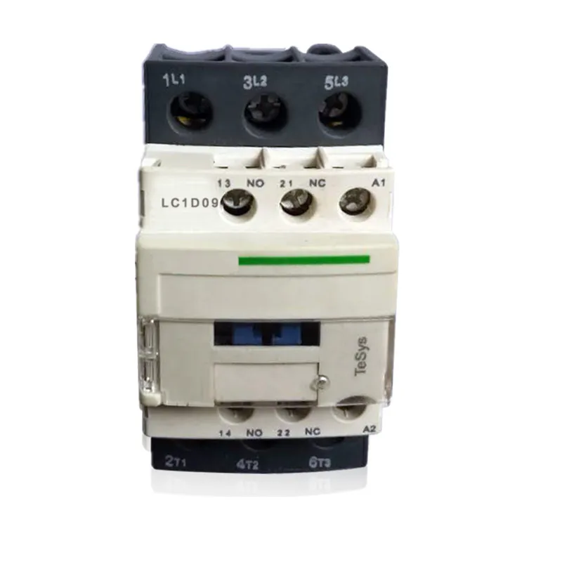
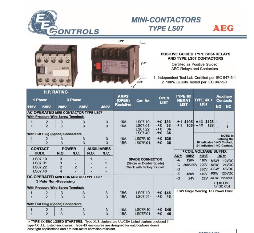
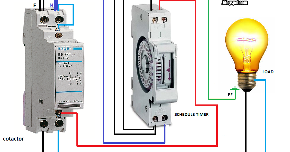
The above diagram is a complete method of single phase motor wiring with circuit breaker and contactor. These lines far exceed the 120 volts ac standard in most homes.
Contactor Wiring Guide For 3 Phase Motor With Circuit Breaker
220v contactor wiring diagram. If not the arrangement wont function as it ought to be. The main advantage in using a contactor is that the switch can be powered by a different and lower power source from the main contactor power supply. Typically a contactor is activated by a remote switch or other controlling electrical device. In the above one phase motor wiring i first connect a 2 pole circuit breaker and after that i connect the supply to motor starter and then i do cont actor coil wiring with normally close push button switch and normally open push button switch and in last i do connection between capacitor. A simple circuit diagram either of the two start buttons will close the contactor either of the stop buttons will open the contactor. 240 volt contactor wiring diagram 220 volt contactor wiring diagram 240 volt coil contactor wiring diagram 240 volt contactor wiring diagram every electrical arrangement consists of various distinct pieces.
Note that one one of the contactor acts as a switch for the start button. In other words a 120 volt. Many large pieces of equipment are powered directly from high voltage lines. Contactor wiring diagram pdf furnas contactor wiring diagram collection how to reverse 220v motor for hanger door 177 best download wiring diagram. How to wire a contactor. 240 volts ac and 480 volts ac are commonly used for these large pieces of.
Each part should be set and connected with different parts in particular way. Wiring a contactor is a safe method for controlling electrical power.


