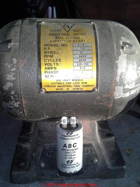
Ladder diagram basics 3 2 wire 3 wire motor control circuit duration. Wondering how a capacitor can be used to start a single phase motor.

Square D Wiring Diagram Book Switch Relay
1 hp motor starter wiring diagram. In this case neutral white is carried through to the motor bypassing the starter altogether. How to connect a portable generator to home supply system three methods a simple circuit diagram of contactor with three phase motor. Click here to view a capacitor start motor circuit diagram for starting a single phase motor. 240 vac motor wiring wiring diagrams hubs single phase motor wiring diagram with capacitor wiring diagram will come with numerous easy to follow wiring diagram directions. Single phase motor wiring diagram with capacitor baldor single phase motor wiring diagram with capacitor single phase fan motor wiring diagram with capacitor single phase motor connection diagram with capacitor every electrical arrangement is made up of various unique pieces. Also read about the speed torque characteristics of these motors along with its different types.
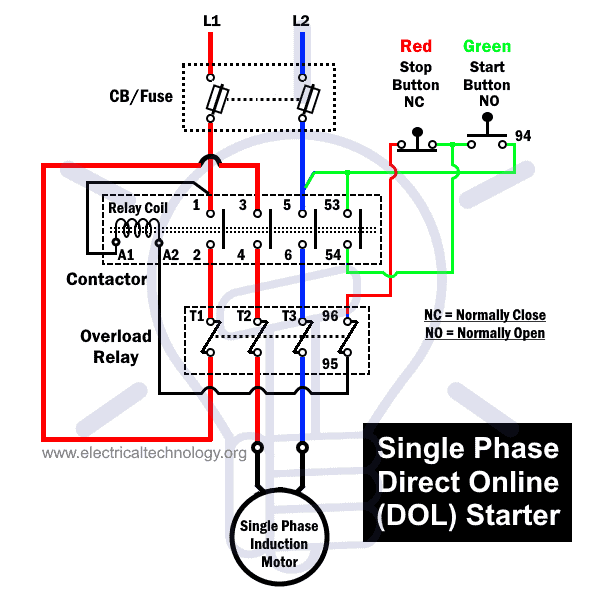
3ø wiring diagrams 1ø wiring diagrams diagram er9 m 3 1 5 9 3 7 11 low speed high speed u1 v1 w1 w2 u2 v2 tk tk thermal overloads two speed stardelta motor switch m 3 0 10v 20v 415v ac 4 20ma outp uts diagram ic2 m 1 240v ac 0 10v outp ut diagram ic3 m 1 0 10v 4 20ma 240v ac outp uts these diagrams are current at the time of publication. T1 is motor 1 out and goes from the starter to the motor. In the above one phase motor wiring i first connect a 2 pole circuit breaker and after that i connect the supply to motor starter and then i do cont actor coil wiring with normally close push button switch and normally open push button switch and in last i do connection between capacitor. Each component ought to be placed and linked to different parts in particular manner. To read a wiring diagram first you need to know exactly what basic components are included in a wiring diagram and also which pictorial icons are used to represent them. The usual aspects in a wiring diagram are ground power supply cord and link outcome devices switches resistors reasoning entrance lights etc.
The above diagram is a complete method of single phase motor wiring with circuit breaker and contactor. This wiring should not be used on 240 volt circuits. Weg motor capacitor wiring diagrams schematics and baldor diagram in. One line diagram of simple contactor circuit. Multi speed 3 phase motor 3 speeds 1 direction power control diagrams. There are single pole starters that should only be used for 120 volt motors.
Baldor reliance industrial motor wiring diagram new wirh baldor. Baldor single phase motor wiring diagram collections of weg motor capacitor wiring diagrams schematics and baldor diagram in. Water pump controller with float switch duration. 5 hp electric motor single phase wiring diagram beautiful single. Three phase electrical wiring installation in home iec nec. L1 is line 1 in and should be the hot black wire.
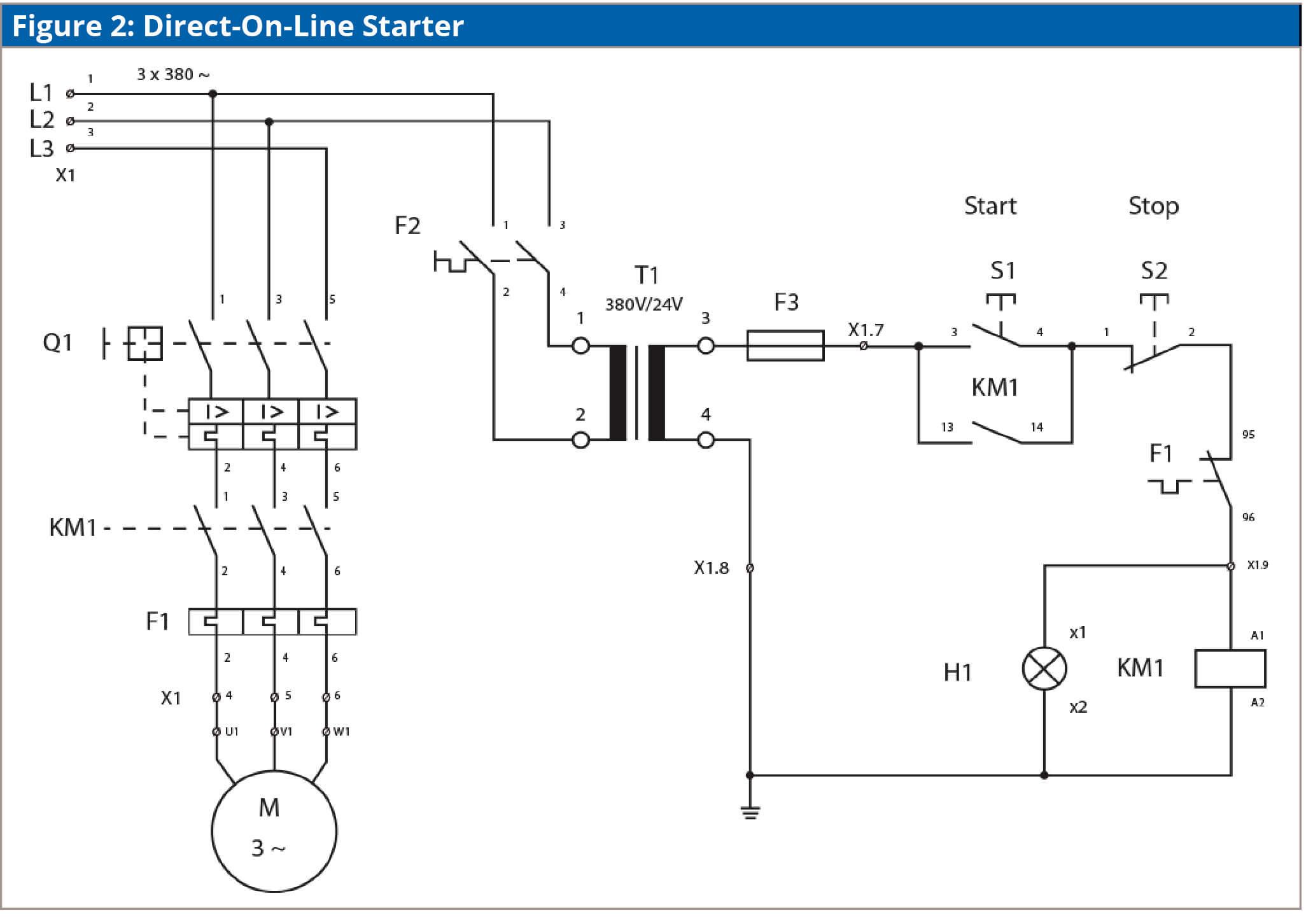
3 phase dol starter control and power wiring diagram. You may also read. It is intended to help all the typical user in building a correct program. Learn how a capacitor start induction run motor is capable of producing twice as much torque of a split phase motor.

