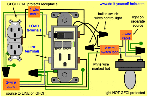
Direct main power supply. By connecting the switch to the load terminals on the last gfci the switch and light are protected against ground faults as well.
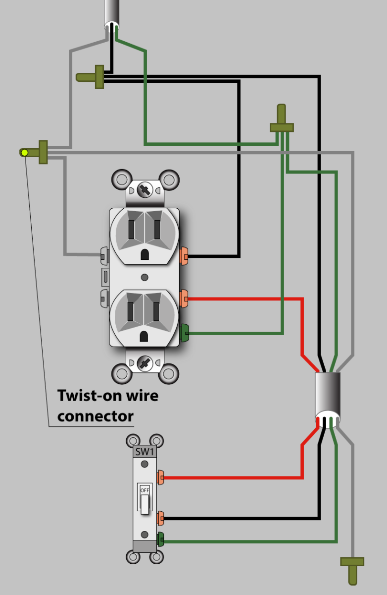
An Electrician Explains How To Wire A Switched Half Hot
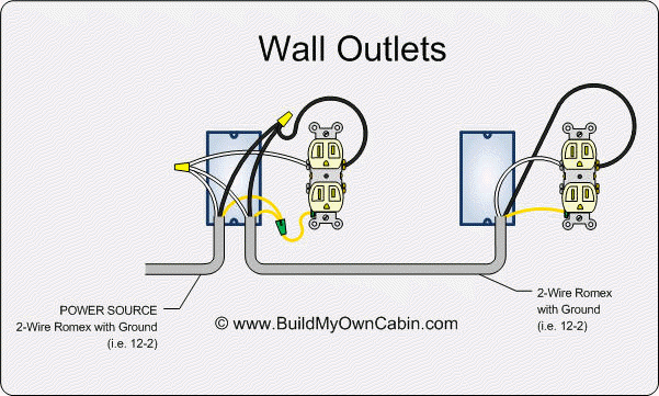
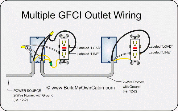
Wiring diagram for gfci plug. Make sure the amp rating of your new gfci outlet matches the amp rating of the wiring and breaker or fuse. Illustrated guide to gfci outlet wiring methods with diagrams and photos for wiring a gfci using the feed through method which will protect more than one outlet. Wiring diagram for a switched gfci combo outlet. It means all the connected loads to the load terminals of gfci are protected. Howtowith geo 354242 views. When it comes to ground fault circuit interrupter or gfci outlets there is always a question as to how to connect the wiresthis is because gfcis have two different sets of terminals.
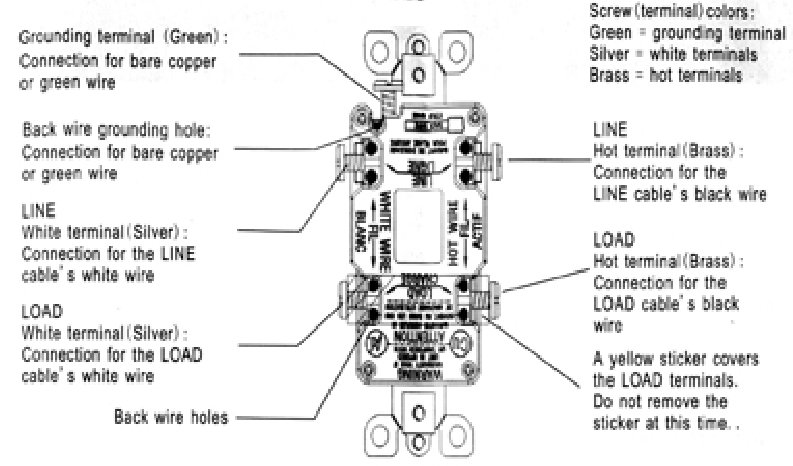
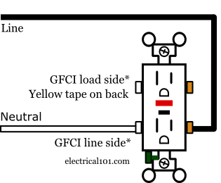
The line terminals and the load terminals. Unscrew the terminal screws of the new gfci outlet until they are difficult to turn. This article and the electrical wiring diagram will show you how to install a gfi using the. How to install a ground fault circuit interrupter gfci outlet plug duration. Tighten the terminal screw. Loosen the silver and brass terminal screws on the line side of the outlet.
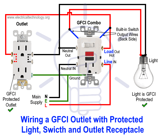
The source hot wire is spliced with one of the switch wires and the other switch wire is connected to the hot line terminal on the device. This gfci wiring method may be found in a bathroom or kitchen where. This diagram illustrates the wiring for a circuit with 2 gfci receptacles followed by a light and switch. Wiring a gfci outlet with combo switch outlet receptacle light switch. A 20 amp gfci outlet the left or neutral plug opening will have both the vertical. In the first wiring diagram the connected load as light bulb is gfci protected as it is control by the combo switch and connected to the load terminals of gfci.
Calculate the minimum box size required for all of the wires plus the gfci see required box size below. If more than 1 black and 1 white conductor are in the electrical box also loosen the load side silver and brass terminal screws. Refer to the diagram above about wiring gfci receptacles for additional help. Then unscrew and pull out the old outlet and count the number of wires in the box. Gfci outlet wiring to protected a light. The source neutral is connected the line neutral terminal.
When you connect only to the line terminals the outlet provides gfci protection only for itself. In the second wiring diagram the lamp is connected directly to the line terminals of gfci ie. In this gfci outlet wiring and installation diagram the combo switch outlet spst single way switch and ordinary outlet is connected to the load side of gfci. Connect the black line hot wire to the brass screw marked line by inserting the wire into the back wire hole. In this diagram the switch built into the combo device is wired to control the gfci outlet itself. Plug a lamp radio or the gfci tester into the outlet to test for power and make sure its off.
