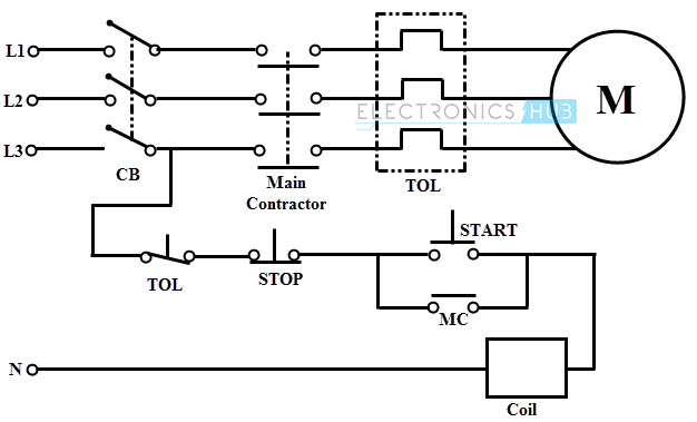
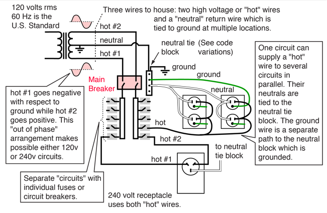
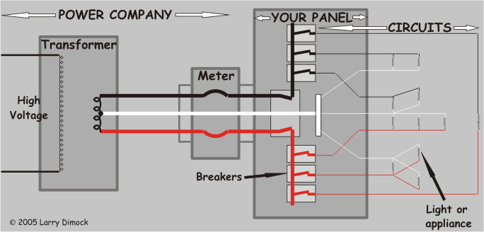
Read electrical wiring diagram. Whats wiring diagram a wiring diagram is a type of schematic that uses abstract pictorial symbols to show all the interconnections of components in a system.

Home Wiring Wikipedia
What are the two types of electrical wiring diagram. Methods of electrical wiring systems wrt taking connection. The uses of these two types of diagrams are compared in table 1. Diagrams will show receptacles lighting interconnecting wire routes and electrical services within a home. Wiring diagrams use electrical symbols like the ladder diagram but they try to show the actual locations of the components. The box is marked with the numbers and alphabets followed by the page number. Wiring diagrams help you identify wires and components as they are found on the equipment.
There are three ways to show electrical circuits. The electrical wiring diagram consists of two types such as a single line wiring diagram and a multi line wiring diagram. An electrical wiring diagram will use different symbols depending on the type but the components remain the same. Doe hdbk 10161 93 electrical diagrams and schematics electrical diagrams and schematics types of electrical diagrams or schematics there are three ways to show electrical circuits. Types of electrical diagrams or schematics. Wiring diagrams are made up of two things.
Majorly the wiring is divided into two types namely parallel wiring and series wiring depending on the way the devices are powered or connected to the supply. Refer to the figure an electrical wiring diagram is surrounded by the rectangular box. Wiring diagrams may also be referred to as connection diagrams. Figure 8 large common electrical components. The two most commonly used are the wiring diagram and the schematic diagram. The two most commonly used are the wiring diagram and the schematic diagram.
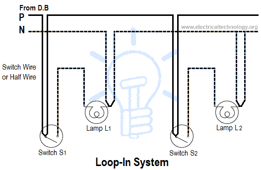
They are wiring schematic and pictorial diagrams. Wiring a process of connecting various accessories for distribution of electrical energy from suppliers meter board to home appliances such as lamps fans and other domestic appliances is known as electrical wiring can be done using two methods which are. Vertical and horizontal lines are used to represent wires and each line represents a single wire that connects between electrical components. They are wiring schematic and pictorial diagrams. The wiring diagram is used for the representation of electrical components in their approximate physical location using their specific symbols and their interconnections using lines. This includes circuit breaker boxes and any alarms that are wired into the system.
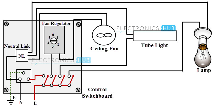
The electrical wiring diagram is a pictorial representation of the circuit which shows the wiring between the parts or elements or equipments. Symbols that represent the components in the circuit and lines that represent the connections between them. Therefore from wiring diagrams.




/cdn.vox-cdn.com/uploads/chorus_image/image/65890030/electrical_wiring_x_banneer.7.jpg)

