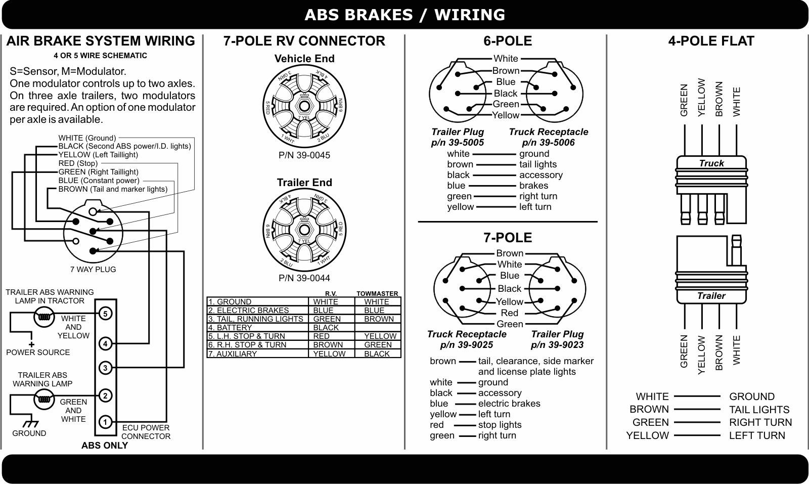
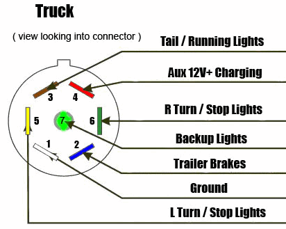
I have included a link to it. The first diagram is a simple set up of two brake lights two indicators and two side lights.
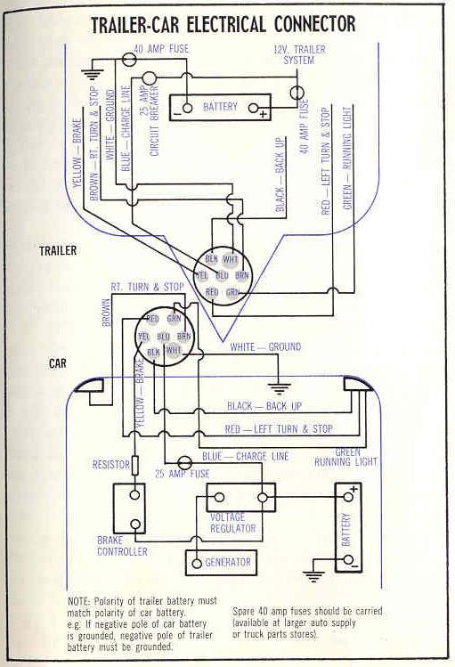
Tractor Trailer Wiring Connector Diagram Connector Diagram
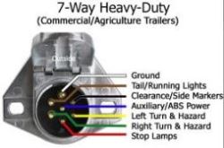
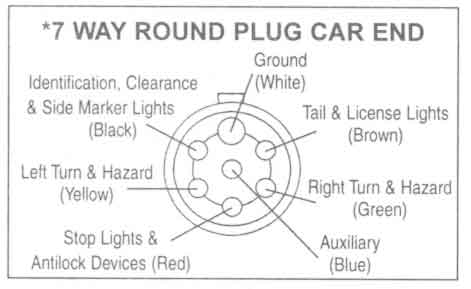
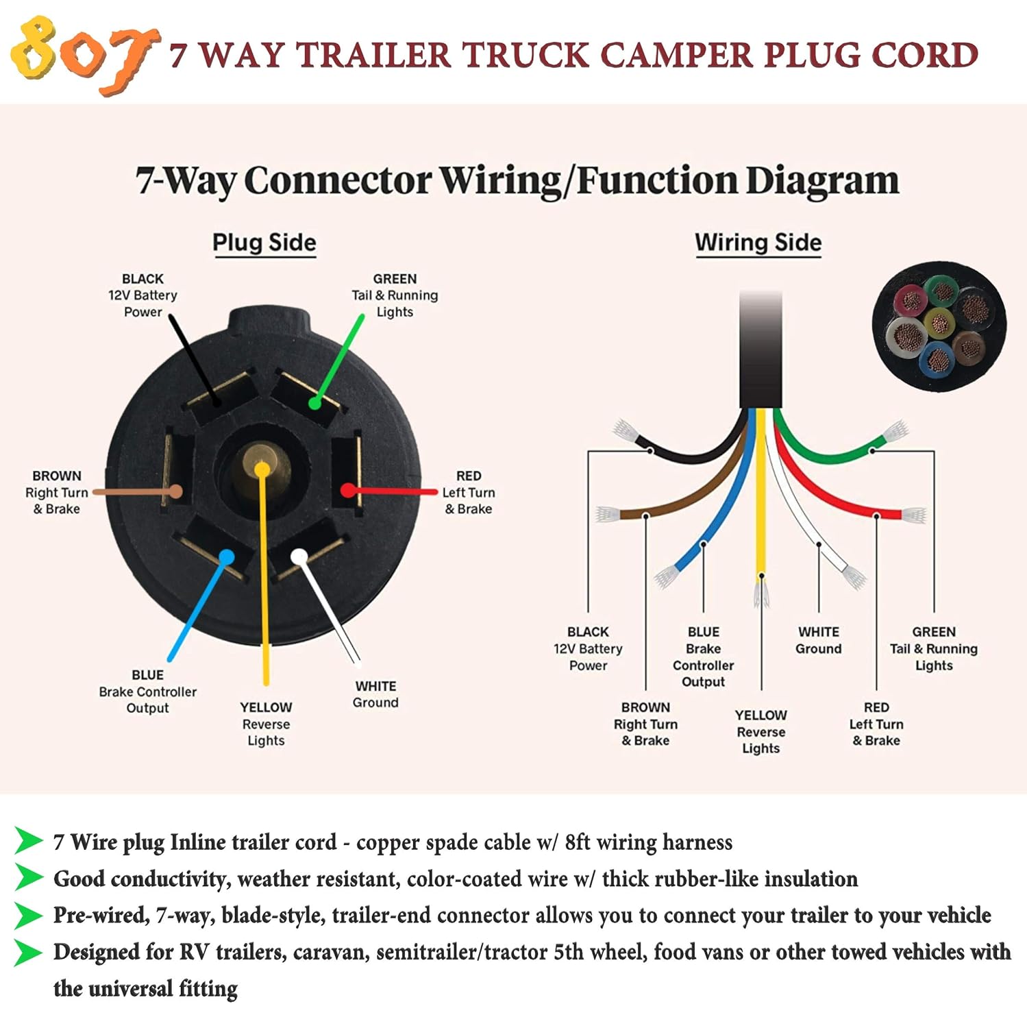
Tractor trailer 7 pin wiring diagrams. Use the 7 pin connector anyway see below and just leave out the last 2 wires. The wiring color codes and wire gauge recommendations for the pollak heavy duty 7 pole round pin trailer wiring connector item pk11700 are listed below. This vehicle is designed not only to travel one place to another but also to take heavy loads. I have also included a picture that shows the typical wiring diagram of a 7 way round pin trailer side connector. It reveals the parts of the circuit as simplified forms as well as the power and also signal links between the tools. 7 pin semi trailer wiring diagram 7 pin round semi trailer wiring diagram 7 pin semi trailer wiring diagram people today comprehend that trailer is a vehicle comprised of rather complicated mechanisms.
These connectors are rated at 40a continuous duty. In the trailer wiring diagram and connector application chart below use the first 5 pins and ignore the rest. This article will be discussing 7 pin semi trailer wiring diagram. As you can see the 7 way round pin trailer connectors do not use the typical pin functions. Variety of 7 pin round trailer wiring diagram. Here are two wiring diagrams for the 7 pin n type trailer electrical plug.
If you dont follow this your trailer or tow vehicle cant be used with any other implement. There is a standard method of wiring a 7 pin trailer connector. If your truck has a built in 7 pin socket but you only need 5 of the pins. I used a small 7 pin round for 10 years and then after replacing the plug multiple times changed to 7 pin flat for the last 15 years and i have never had a problem with a flat connector. I had one vehicle with a 12 pin socket and a trailer with a 7 pin connector and they played happily for years. 7 way plug wiring diagram standard wiring post purpose wire color tm park light green battery feed black rt right turnbrake light brown lt left turnbrake light red s trailer electric brakes blue gd ground white a accessory yellow this is the most common standard wiring scheme for rv plugs and the one used by major auto manufacturers today.
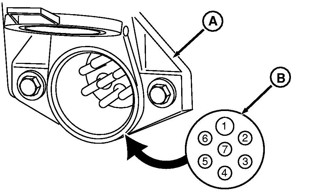
Click on the image below to enlarge it. Pin number 1 is self grounded die cast only with a peak rating of 70a and accepts wire. The second diagram shows two brake lights two indicators two side lights and a fog light. White ground return 8 gauge black clearance side marker identification 12 gauge. A wiring diagram is a simplified standard pictorial depiction of an electric circuit. Click on the image below to enlarge it.
7 pin heavy duty trailer wiring diagram manufactured in accordance with the saej560 standard and in accordance with the australian standard as4735 2003 as required for vehicles and trailers over 35 tonnes. I do have a handy trailer wiring faq article that would be perfect for you.
