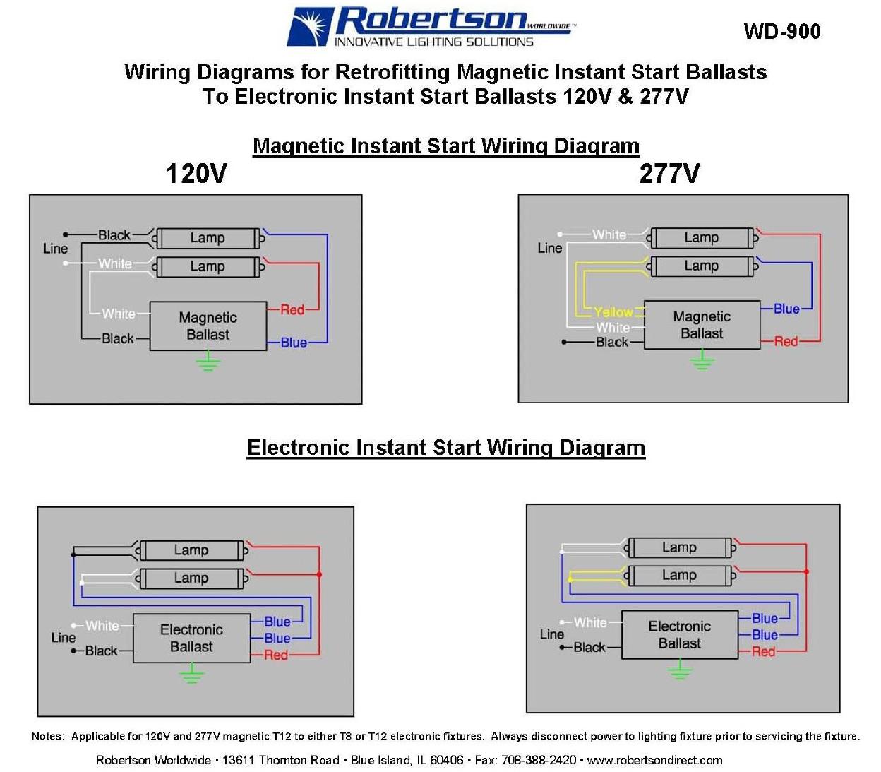
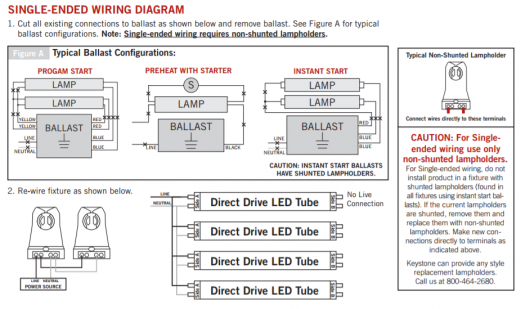
Wiring refer to the wiring diagrams on the back page for the appropriate wiring of lamps and ballast. Number of lamps to be operated in emergency mode.

Details About Iota I 32 Tbts Series D Emergency Lighting Ballast For 2 4 Ft Lamp 120 277v 60hz
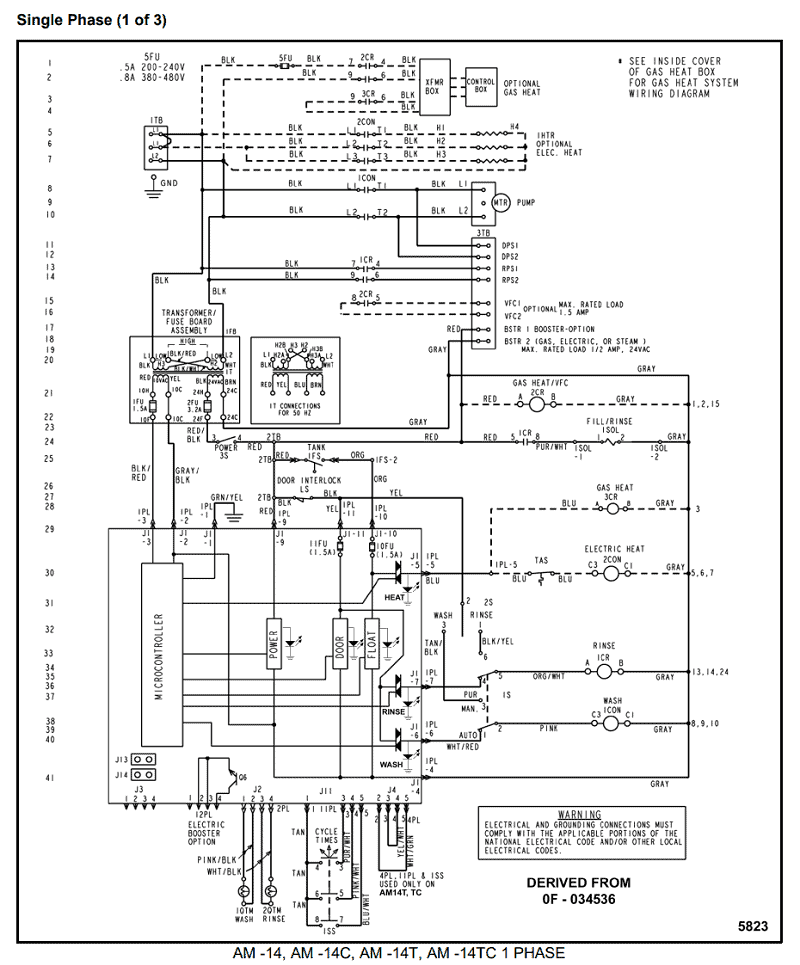
Iota i 32 emergency ballast wiring diagram. Lighting equipment instruction manual this unit. When battery packs are remote mounted consult customer service for the maximum allowable distance between the battery pack and the lamp. The emergency ballast wiring guide. Use the navigation window and select the emergency ballast for which the diagram is needed then scroll through the list of applications to find the. A wiring diagram is a streamlined traditional photographic representation of an electric circuit. Replacementiota i 24 emergency ballast this brand new replacement emergency ballast pack for iota i 24 consists of a high temperature nickel cadmium battery charger and inverter circuit in a single box.
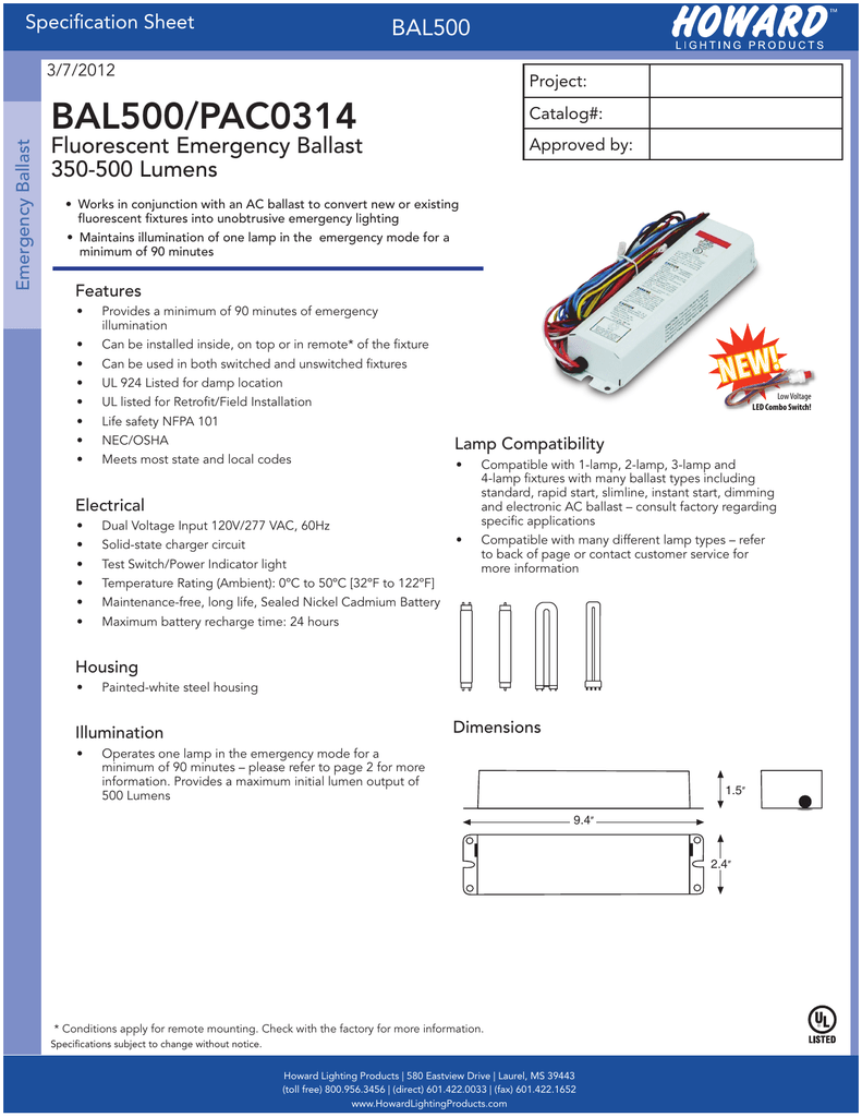
In the event of power loss this emergency ballast will provide backup power to 1 fluorescent lamp up to 500 lumens for 90 minutes. The optional top mounting kit catalog no. Ballast in an old magnetic t12 ballast fixture. The iota i 32 tbts emergency ballast offers emergency lighting possibilities to your new or old fluorescent fixtures. The i 32 may also be mounted on top of the fixture. A1 a1 test switch charge indicator unit connector white red whtblk flex b.
Mount the i 32 in the ballast channel at least 12 away from the ac. Use the navigation window and select the emergency ballast for which the diagram is needed then scroll through the list of applications to find the. The i 32 fluorescent emergency ballast from iota engineering allows the same fixture to be used for both normal and emergency operation. Emergency light switch wiring diagram. Learn the basics for wiring and testing the iota ilb cp emergency driver. The unit contains a battery charger and inverter circuit in a single can.
In the event of a power failure the i 32 switches to the emergency mode and operates one of the existing lamps for 90 minutes. Mount the i 320 in the ballast channel at least 2 away from the ac. The emergency ballast wiring guide. Mounting the i 32 remove the ballast channel cover. Emergi lite iota fpdl7 13 fpdl10 42 fpdl18 26 fpdl10 42 d fps 80d fps 500 fps 540 fps 825 fps hl fpsi 24 fpsi 32. It reveals the components of the circuit as simplified shapes and the power and also signal connections between the tools.
Collection of fluorescent emergency ballast wiring diagram. Durable steel housing protects the battery charger and electronic circuit. Tmk 32 may be ordered separately from customer service. The iota i 24 replacement emergency ballast battery works with or without an ac ballast to convert new or existing fluorescent fixtures into emergency lighting. A wiring diagram is a streamlined traditional photographic depiction of an electric circuit. I 32 isl 54 isl 540 iota.
Collection of iota emergency ballast wiring diagram. A wiring diagram is a kind of schematic which makes use of abstract photographic icons to reveal all the affiliations of components in a system. The i 32 can be used with most 2 4 t8 thru t12 and.



.jpg)

